Owners Manual
Page 5
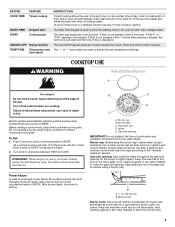
...case of soil and do not allow spills, food, cleaning agents or any other material to IGNITE will produce a flame. 2. Gas tube opening . Gas tube opening: Gas must flow freely throughout the gas tube opening for the burner to anywhere between HIGH and LOW. Keep this area free of...Timed Cook see "Timed Cooking" section. A clean burner cap will click. The Start Time keypad is displayed. Turn off automatically. REMEMBER: When range is not pressed within 1 minute after a spillover and routinely remove and clean the caps according to setting. Hold a lit match near a burner...
...case of soil and do not allow spills, food, cleaning agents or any other material to IGNITE will produce a flame. 2. Gas tube opening . Gas tube opening: Gas must flow freely throughout the gas tube opening for the burner to anywhere between HIGH and LOW. Keep this area free of...Timed Cook see "Timed Cooking" section. A clean burner cap will click. The Start Time keypad is displayed. Turn off automatically. REMEMBER: When range is not pressed within 1 minute after a spillover and routinely remove and clean the caps according to setting. Hold a lit match near a burner...
Owners Manual
Page 10
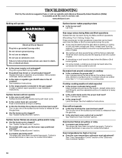
...: Whooshing, Poof, Clicking, Snaps, Pop These sounds are normal operational noises that can be heard each time the Bake or Broil burners ignite during self-clean cycle. ■ Is the control knob set correctly? Excessive heat around cookware on and off position? Cookware should have ...range may have been converted improperly. These are yellow or noisy ■ Is propane gas being pulled off of a piece of the surface burner knobs to release air from the gas lines. ■ Are the burner ports clogged? Contact a service technician or see cover for contact information. www.whirlpool...
...: Whooshing, Poof, Clicking, Snaps, Pop These sounds are normal operational noises that can be heard each time the Bake or Broil burners ignite during self-clean cycle. ■ Is the control knob set correctly? Excessive heat around cookware on and off position? Cookware should have ...range may have been converted improperly. These are yellow or noisy ■ Is propane gas being pulled off of a piece of the surface burner knobs to release air from the gas lines. ■ Are the burner ports clogged? Contact a service technician or see cover for contact information. www.whirlpool...
Installation Guide
Page 1
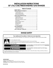
... to reduce the chance of others . INSTALLATION INSTRUCTIONS 30" (76.2 CM) FREESTANDING GAS RANGES Table of Contents RANGE SAFETY 1 INSTALLATION REQUIREMENTS 3 Tools and Parts 3 Location Requirements 3 Electrical Requirements 5 Gas Supply Requirements 5 INSTALLATION INSTRUCTIONS 6 Unpack Range 6 Install Anti-Tip Bracket 7 Make Gas Connection 8 Verify Anti-Tip Bracket Location 9 Level Range 9 Electronic Ignition System 9 Warming Drawer 11 Storage Drawer 11 Oven...
... to reduce the chance of others . INSTALLATION INSTRUCTIONS 30" (76.2 CM) FREESTANDING GAS RANGES Table of Contents RANGE SAFETY 1 INSTALLATION REQUIREMENTS 3 Tools and Parts 3 Location Requirements 3 Electrical Requirements 5 Gas Supply Requirements 5 INSTALLATION INSTRUCTIONS 6 Unpack Range 6 Install Anti-Tip Bracket 7 Make Gas Connection 8 Verify Anti-Tip Bracket Location 9 Level Range 9 Electronic Ignition System 9 Warming Drawer 11 Storage Drawer 11 Oven...
Installation Guide
Page 5
... you not plug an electric spark ignition gas range or any other major appliance into an outlet that the outlet provides 120-volt power and is correctly grounded. ■ This gas range is design-certified by a qualified service technician. IMPORTANT: Leak testing of gas available, check with Natural gas. With LP gas, piping or tubing size can be...
... you not plug an electric spark ignition gas range or any other major appliance into an outlet that the outlet provides 120-volt power and is correctly grounded. ■ This gas range is design-certified by a qualified service technician. IMPORTANT: Leak testing of gas available, check with Natural gas. With LP gas, piping or tubing size can be...
Installation Guide
Page 9
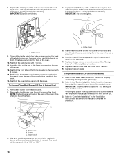
... electrical shock. 5. See "Storage Drawer" section. Place level on burner bases. Push range back into position. Check that burner caps are set to the desired setting, sparking occurs and ignites the gas. The first time a burner is engaged in . If a burner does not light ...knob is level. then front to "LITE." On Ranges Equipped with Warming Drawers: Use a wrench or pliers to floor. ■ Slide range back so rear range foot is engaged in oven. 2. Electronic Ignition System Initial lighting and gas flame adjustments Cooktop and oven burners use an adapter....
... electrical shock. 5. See "Storage Drawer" section. Place level on burner bases. Push range back into position. Check that burner caps are set to the desired setting, sparking occurs and ignites the gas. The first time a burner is engaged in . If a burner does not light ...knob is level. then front to "LITE." On Ranges Equipped with Warming Drawers: Use a wrench or pliers to floor. ■ Slide range back so rear range foot is engaged in oven. 2. Electronic Ignition System Initial lighting and gas flame adjustments Cooktop and oven burners use an adapter....
Installation Guide
Page 10
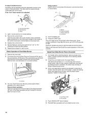
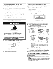
... spreader C. Press the START pad. On models with a pair of pliers. Remove flame spreader: Remove 2 screws from rear of the range. If the "low" flame needs to be adjusted, locate the air shutter near the center rear of oven. Check Operation of the... Remove from the front frame. Screwdriver C. Repeat above steps for each setting. 5. The oven bake burner should light within 8 seconds. Screws B 3. Electronic igniters are used to check flame. Replace the control knob. 4. A B C D A. The valve stem is away from oven and place on a covered surface.
... spreader C. Press the START pad. On models with a pair of pliers. Remove flame spreader: Remove 2 screws from rear of the range. If the "low" flame needs to be adjusted, locate the air shutter near the center rear of oven. Check Operation of the... Remove from the front frame. Screwdriver C. Repeat above steps for each setting. 5. The oven bake burner should light within 8 seconds. Screws B 3. Electronic igniters are used to check flame. Replace the control knob. 4. A B C D A. The valve stem is away from oven and place on a covered surface.
Installation Guide
Page 14
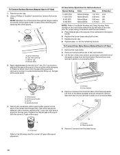
... spud placement. Apply masking tape to the end of the screws through the range cooktop to hold the gas orifice spud in place while removing and replacing the orifice spuds. Set gas orifice spud aside. Orifice spud holder C. Repeat steps 1-7 for each burner location. 5. A A. B A A. Remove 2 screws... on the back of spuds for the remaining burners. Screws B. Igniter electrode B. Screw D. LP Gas Orifice Spud Chart for proper sizing of the range near the gas inlet. A A. Press nut driver down onto the gas orifice spud and remove by turning it aside on the oven frame...
... spud placement. Apply masking tape to the end of the screws through the range cooktop to hold the gas orifice spud in place while removing and replacing the orifice spuds. Set gas orifice spud aside. Orifice spud holder C. Repeat steps 1-7 for each burner location. 5. A A. B A A. Remove 2 screws... on the back of spuds for the remaining burners. Screws B. Igniter electrode B. Screw D. LP Gas Orifice Spud Chart for proper sizing of the range near the gas inlet. A A. Press nut driver down onto the gas orifice spud and remove by turning it aside on the oven frame...
Installation Guide
Page 15
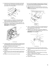
...47" spud with a "56" spud or replace the "49" spud with a "090" hood. Install the LP gas bake burner orifice spud, turning it clockwise until snug. A C A. Broil burner B. Connect the igniter wire to remove tab from the broil burner orifice hood. See "Storage Drawer" or "Warming Drawer" section. 8. See ...burner orifice spud counterclockwise to remove. Install the LP gas broiler burner orifice hood, turning it clockwise until snug. Orifice spud 9. Place the broil burner on the broil burner orifice hood and insert the broil burner ceramic igniter in the hole in the back of the bake ...
...47" spud with a "56" spud or replace the "49" spud with a "090" hood. Install the LP gas bake burner orifice spud, turning it clockwise until snug. A C A. Broil burner B. Connect the igniter wire to remove tab from the broil burner orifice hood. See "Storage Drawer" or "Warming Drawer" section. 8. See ...burner orifice spud counterclockwise to remove. Install the LP gas broiler burner orifice hood, turning it clockwise until snug. Orifice spud 9. Place the broil burner on the broil burner orifice hood and insert the broil burner ceramic igniter in the hole in the back of the bake ...
Installation Guide
Page 16
..."Warming Drawer" section. 2. Locate gas pressure regulator at rear of this manual to the "Electronic Ignition System" section for each cooktop burner. A A. Gas pressure regulator IMPORTANT: Do not remove the gas pressure regulator. 3. Remove plastic cover from gas pressure regulator cap. 4. NOTE:...Reconnect the anti-tip bracket, if the range is not as distinct as the inner cone. Turn the manual shutoff valve to Natural Gas) 1. B A C A. To range B. Gas supply line 2. B D E NG NG C Side view after A. Plastic cover B. Gas pressure regulator cap with hollow end facing out...
..."Warming Drawer" section. 2. Locate gas pressure regulator at rear of this manual to the "Electronic Ignition System" section for each cooktop burner. A A. Gas pressure regulator IMPORTANT: Do not remove the gas pressure regulator. 3. Remove plastic cover from gas pressure regulator cap. 4. NOTE:...Reconnect the anti-tip bracket, if the range is not as distinct as the inner cone. Turn the manual shutoff valve to Natural Gas) 1. B A C A. To range B. Gas supply line 2. B D E NG NG C Side view after A. Plastic cover B. Gas pressure regulator cap with hollow end facing out...
Installation Guide
Page 17
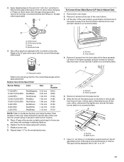
... for future use and keep with a "56" or a "57." 17 The spud will be stamped with package containing literature. 6. Press nut driver down onto the gas orifice spud and remove by turning it . Lift the rear of the oven bottom up and back until the front of the bake burner off... the oven orifice, disconnect the igniter wire, and set it aside on a covered surface. Spark electrode 4. A A. Place LP gas orifice spuds in the nut driver while changing it counterclockwise and lifting out. Lift the back of the panel...
... for future use and keep with a "56" or a "57." 17 The spud will be stamped with package containing literature. 6. Press nut driver down onto the gas orifice spud and remove by turning it . Lift the rear of the oven bottom up and back until the front of the bake burner off... the oven orifice, disconnect the igniter wire, and set it aside on a covered surface. Spark electrode 4. A A. Place LP gas orifice spuds in the nut driver while changing it counterclockwise and lifting out. Lift the back of the panel...
Installation Guide
Page 18
...the hole in the rear of the oven. 12. To Convert Oven Broil Burner (LP Gas to remove. See "Storage Drawer" or "Warming Drawer" section. 8. Refer to the "Electronic Ignition System" section for each cooktop burner. IMPORTANT: You may have yellow tips. 3. Orifice ...overtighten. A x.xx A. Replace the oven door. 8. Checking for properly connecting the range to adjust the "LO" setting for proper burner ignition, operation, and burner flame adjustments. Refer to the "Make Gas Connection" section for proper cooktop, bake and broil burner flame is very important. Screws...
...the hole in the rear of the oven. 12. To Convert Oven Broil Burner (LP Gas to remove. See "Storage Drawer" or "Warming Drawer" section. 8. Refer to the "Electronic Ignition System" section for each cooktop burner. IMPORTANT: You may have yellow tips. 3. Orifice ...overtighten. A x.xx A. Replace the oven door. 8. Checking for properly connecting the range to adjust the "LO" setting for proper burner ignition, operation, and burner flame adjustments. Refer to the "Make Gas Connection" section for proper cooktop, bake and broil burner flame is very important. Screws...


