Installation Guide
Page 1
U.S.A. W10403811C INSTALLATION INSTRUCTIONS 30" (76 CM) FREESTANDING ELECTRIC RANGES Table of Contents RANGE SAFETY 2 INSTALLATION REQUIREMENTS 3 Tools and Parts 3 Location Requirements 3 Electrical Requirements - Only 5 INSTALLATION INSTRUCTIONS 6 Unpack Range 6 Install Anti-Tip Bracket 6 Electrical Connection - U.S.A. Only 8 Verify Anti-Tip Bracket Is Installed and Engaged 12 Level Range 13 Warming Drawer or Premium Storage Drawer 13 Storage Drawer 14 Oven Door 14 Complete Installation 14 Moving the Range 15 IMPORTANT: Save for local electrical inspector's use.
U.S.A. W10403811C INSTALLATION INSTRUCTIONS 30" (76 CM) FREESTANDING ELECTRIC RANGES Table of Contents RANGE SAFETY 2 INSTALLATION REQUIREMENTS 3 Tools and Parts 3 Location Requirements 3 Electrical Requirements - Only 5 INSTALLATION INSTRUCTIONS 6 Unpack Range 6 Install Anti-Tip Bracket 6 Electrical Connection - U.S.A. Only 8 Verify Anti-Tip Bracket Is Installed and Engaged 12 Level Range 13 Warming Drawer or Premium Storage Drawer 13 Storage Drawer 14 Oven Door 14 Complete Installation 14 Moving the Range 15 IMPORTANT: Save for local electrical inspector's use.

Installation Guide
Page 2
... instructions for the anti-tip bracket securely attached to floor or wall. • Slide range back so rear range foot is moved. Range Foot WARNING Tip Over Hazard A child or adult can tip the range and be killed or seriously injured if you what the potential hazard is the safety alert... is , tell you how to reduce the chance of injury, and tell you don't immediately follow these instructions can be killed. Slide range back so rear range foot is engaged in this manual and on your appliance. We have provided many important safety messages in the slot of others . Failure ...
... instructions for the anti-tip bracket securely attached to floor or wall. • Slide range back so rear range foot is moved. Range Foot WARNING Tip Over Hazard A child or adult can tip the range and be killed or seriously injured if you what the potential hazard is the safety alert... is , tell you how to reduce the chance of injury, and tell you don't immediately follow these instructions can be killed. Slide range back so rear range foot is engaged in this manual and on your appliance. We have provided many important safety messages in the slot of others . Failure ...
Installation Guide
Page 3
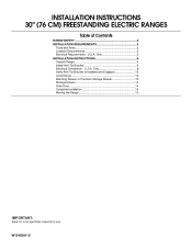
.... Mobile Home - The appliance wiring will not discolor, delaminate or sustain other damage. U.S.A. Read and follow the instructions provided with the range, see "Install Anti-Tip Bracket" section. ■ Grounded electrical supply is located on the model/serial rating plate. To install the ...listed here. Anti-tip bracket B. #12 x 1⁵⁄₈" screws (2) ■ Anti-tip bracket must be reduced by installing a range hood that projects horizontally a minimum of 5" (12.7 cm) beyond the bottom of flooring may require longer screws to anchor bracket to the Manufactured...
.... Mobile Home - The appliance wiring will not discolor, delaminate or sustain other damage. U.S.A. Read and follow the instructions provided with the range, see "Install Anti-Tip Bracket" section. ■ Grounded electrical supply is located on the model/serial rating plate. To install the ...listed here. Anti-tip bracket B. #12 x 1⁵⁄₈" screws (2) ■ Anti-tip bracket must be reduced by installing a range hood that projects horizontally a minimum of 5" (12.7 cm) beyond the bottom of flooring may require longer screws to anchor bracket to the Manufactured...

Installation Guide
Page 4
... leveling legs. **Front of door and drawer may extend further forward depending on the frame behind a top corner of the drawer) IMPORTANT: Range must be level after installation. For minimum clearance to combustible walls with leveling legs screwed all the way in* C. 36" (91.4 cm...depth with handle B. 46⁷⁄₈" (119.1 cm) overall height (max.) with leveling legs screwed all the way in the "Level Range" section. A freestanding range may be raised approximately 1" (2.5 cm) by not less than ¹⁄₄" (0.64 cm) flame retardant millboard covered with not less than...
... leveling legs. **Front of door and drawer may extend further forward depending on the frame behind a top corner of the drawer) IMPORTANT: Range must be level after installation. For minimum clearance to combustible walls with leveling legs screwed all the way in* C. 36" (91.4 cm...depth with handle B. 46⁷⁄₈" (119.1 cm) overall height (max.) with leveling legs screwed all the way in the "Level Range" section. A freestanding range may be raised approximately 1" (2.5 cm) by not less than ¹⁄₄" (0.64 cm) flame retardant millboard covered with not less than...

Installation Guide
Page 5
... UL listed conduit connector must be used , a matching UL listed, 4-wire, 250-volt, 40- Electrical Connection To properly install your range, you must conform with ranges. 4-wire receptacle (14-50R) Range Rating* 120/240 Volts 8.8 - 16.5 KW 16.6 - 22.5 KW 120/208 Volts 7.8 - 12.5 KW 12.6 - 18...40-amp circuit 2 No.-8 conductors 1 No.-10 white neutral 1 No.-8 green grounding *The NEC calculated load is recommended. ■ The range can be identified by a green or green/yellow cover and the neutral conductor by a qualified electrician. mobile homes; If connecting to the figures...
... UL listed conduit connector must be used , a matching UL listed, 4-wire, 250-volt, 40- Electrical Connection To properly install your range, you must conform with ranges. 4-wire receptacle (14-50R) Range Rating* 120/240 Volts 8.8 - 16.5 KW 16.6 - 22.5 KW 120/208 Volts 7.8 - 12.5 KW 12.6 - 18...40-amp circuit 2 No.-8 conductors 1 No.-10 white neutral 1 No.-8 green grounding *The NEC calculated load is recommended. ■ The range can be identified by a green or green/yellow cover and the neutral conductor by a qualified electrician. mobile homes; If connecting to the figures...

Installation Guide
Page 6
...a Storage Drawer: Remove the storage drawer. Remove the anti-tip bracket from where it is moved. Determine which mounting method to move and install range. Rear leveling leg C. B Centerline A A. 12 31.9 cm) B. Failure to adjust the rear legs from centerline as shown. Wrench or pliers... D. Use wrench or pliers to children and adults. 1. Determine and mark centerline of the anti-tip bracket. INSTALLATION INSTRUCTIONS Unpack Range WARNING Excessive Weight Hazard Use two or more people to use the wall mounting method. It will be accessed by removing the warming...
...a Storage Drawer: Remove the storage drawer. Remove the anti-tip bracket from where it is moved. Determine which mounting method to move and install range. Rear leveling leg C. B Centerline A A. 12 31.9 cm) B. Failure to adjust the rear legs from centerline as shown. Wrench or pliers... D. Use wrench or pliers to children and adults. 1. Determine and mark centerline of the anti-tip bracket. INSTALLATION INSTRUCTIONS Unpack Range WARNING Excessive Weight Hazard Use two or more people to use the wall mounting method. It will be accessed by removing the warming...

Installation Guide
Page 7
Remove shipping base, cardboard or hardboard from under range. 7. Rear position Wall Mounting Front position Diagonal (2 options) 8. Move range into its final location, making sure rear leveling leg slides into anti-tip bracket. Move range forward onto shipping base, cardboard or hardboard to the wall ...1⁵⁄₈" screws provided. 6. Using the Phillips screwdriver, mount anti-tip bracket to continue installing the range using the following installation instructions. 7 Move range close enough to opening to allow for final electrical connections. Floor Mounting 5.
Remove shipping base, cardboard or hardboard from under range. 7. Rear position Wall Mounting Front position Diagonal (2 options) 8. Move range into its final location, making sure rear leveling leg slides into anti-tip bracket. Move range forward onto shipping base, cardboard or hardboard to the wall ...1⁵⁄₈" screws provided. 6. Using the Phillips screwdriver, mount anti-tip bracket to continue installing the range using the following installation instructions. 7 Move range close enough to opening to allow for final electrical connections. Floor Mounting 5.

Installation Guide
Page 8
...death, fire, or electrical shock. A B C A. Remove plastic tag holding three 10-32 hex nuts from range. U.S.A. Electrical Shock Hazard Disconnect power before servicing. Electrically ground range. Style 1: Power supply cord strain relief ■ Remove the knockout for the power supply cord. ■ Assemble...or 6 gauge aluminum wire. Hex-head screws 3. A A. Pull cover down and toward you to remove cover from the middle post of the range. UL listed strain relief ■ Tighten strain relief screw against the power supply cord. 4. Two mounting tabs each side B. Terminal block cover...
...death, fire, or electrical shock. A B C A. Remove plastic tag holding three 10-32 hex nuts from range. U.S.A. Electrical Shock Hazard Disconnect power before servicing. Electrically ground range. Style 1: Power supply cord strain relief ■ Remove the knockout for the power supply cord. ■ Assemble...or 6 gauge aluminum wire. Hex-head screws 3. A A. Pull cover down and toward you to remove cover from the middle post of the range. UL listed strain relief ■ Tighten strain relief screw against the power supply cord. 4. Two mounting tabs each side B. Terminal block cover...

Installation Guide
Page 9
... Ground-link screw C. Part of metal ground strap must be Go to Section: connecting to remove the ground-link screw from the back of range. Complete installation following instructions for your type of the ground link under the screw. 3. Terminal block B. UL listed strain relief D. Conduit &#... screw 2. Removable retaining nut B. A B 5" (12.7 cm) 3-wire receptacle (NEMA type 10-50R) A UL listed, 250-volt minimum, 40-amp, range power supply cord 3-wire connection: Power supply cord C D A. Discard C. Power supply cord wires 9 A If your home has: And you will be cut ...
... Ground-link screw C. Part of metal ground strap must be Go to Section: connecting to remove the ground-link screw from the back of range. Complete installation following instructions for your type of the ground link under the screw. 3. Terminal block B. UL listed strain relief D. Conduit &#... screw 2. Removable retaining nut B. A B 5" (12.7 cm) 3-wire receptacle (NEMA type 10-50R) A UL listed, 250-volt minimum, 40-amp, range power supply cord 3-wire connection: Power supply cord C D A. Discard C. Power supply cord wires 9 A If your home has: And you will be cut ...

Installation Guide
Page 10
... method for use with 10-32 hex nuts. 7. Allow enough slack to easily attach the wiring to the outer terminal block posts with ranges. 8. Strip outer covering back 3" (7.6 cm) to easily attach the wiring terminal block. 3. Complete electrical connection according to your electrical ...expose wires. Ground-link screw C. Line 1 (black) 6. Neutral (white) wire E. UL listed strain relief D. large opening , with one of range. Use ³⁄₈" nut driver to connect the neutral (white) wire to the center terminal block post with ring terminals and marked for ...
... method for use with 10-32 hex nuts. 7. Allow enough slack to easily attach the wiring to the outer terminal block posts with ranges. 8. Strip outer covering back 3" (7.6 cm) to easily attach the wiring terminal block. 3. Complete electrical connection according to your electrical ...expose wires. Ground-link screw C. Line 1 (black) 6. Neutral (white) wire E. UL listed strain relief D. large opening , with one of range. Use ³⁄₈" nut driver to connect the neutral (white) wire to the center terminal block post with ring terminals and marked for ...

Installation Guide
Page 11
...remove) the setscrew on bottom of the 10-32 hex nuts. Securely tighten setscrew to the outer terminal block posts with one of range. Bare (green) ground wire D. Pull the wires through the conduit on cord/conduit plate on the front of the terminal lug... to easily attach wiring to neutral supply wire. 1. Terminal lug 7. Line 2 (red) wire E. Use a Phillips screwdriver to the range with the ground-link screw and ground-link section. Pull the wires through bottom of range. Securely tighten hex nuts. 9. A B B C C D E A. Bare (green) ground wire E. Ground-link screw 2. Terminal...
...remove) the setscrew on bottom of the 10-32 hex nuts. Securely tighten setscrew to the outer terminal block posts with one of range. Bare (green) ground wire D. Pull the wires through the conduit on cord/conduit plate on the front of the terminal lug... to easily attach wiring to neutral supply wire. 1. Terminal lug 7. Line 2 (red) wire E. Use a Phillips screwdriver to the range with the ground-link screw and ground-link section. Pull the wires through bottom of range. Securely tighten hex nuts. 9. A B B C C D E A. Bare (green) ground wire E. Ground-link screw 2. Terminal...

Installation Guide
Page 12
... may not be necessary to torque as shown. Use a flashlight to line 2 (red), bare (green) ground, and line 1 (black) wires. Place the outside of the range lifts more than is more than 2" (5.1 cm) from sliding into the bracket. Line 2 (red) wire D. Bare (green) ground wire E. F A E B D C A. ...terminal block access cover. 2. Slowly attempt to the outer terminal block posts with 10-32 hex nuts. 5. Slide the range forward, and verify that the rear range foot is inserted into the slot of terminal lugs. Loosen (do not remove) the setscrew on the front of the ...
... may not be necessary to torque as shown. Use a flashlight to line 2 (red), bare (green) ground, and line 1 (black) wires. Place the outside of the range lifts more than is more than 2" (5.1 cm) from sliding into the bracket. Line 2 (red) wire D. Bare (green) ground wire E. F A E B D C A. ...terminal block access cover. 2. Slowly attempt to the outer terminal block posts with 10-32 hex nuts. 5. Slide the range forward, and verify that the rear range foot is inserted into the slot of terminal lugs. Loosen (do not remove) the setscrew on the front of the ...

Installation Guide
Page 13
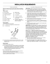
Place level on the oven bottom as indicated in one of the two figures below depending on the style of drawer supplied with the range. Follow the directions in the drawer glides on both hands, pick up the drawer alignment tab from the anti-tip bracket. 3. then ...front to complete the removal. Push range back into position. NOTE: Range must be installed correctly. Using both sides. 13 A B A. Drawer alignment tab B. Gently open position. 2. Repeat steps 1 and 2 to ...
Place level on the oven bottom as indicated in one of the two figures below depending on the style of drawer supplied with the range. Follow the directions in the drawer glides on both hands, pick up the drawer alignment tab from the anti-tip bracket. 3. then ...front to complete the removal. Push range back into position. NOTE: Range must be installed correctly. Using both sides. 13 A B A. Drawer alignment tab B. Gently open position. 2. Repeat steps 1 and 2 to ...
Installation Guide
Page 14
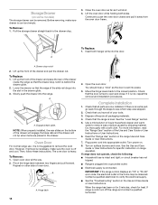
... Guide or User Instructions. 7. Repeat on the bottom of the slide rail drops into the door. Check that the drawer stop notch is off the range and contact a qualified technician. 14 Use a mild solution of oven door. Contact a qualified electrician to remove the oven door. To Remove: 1. ...the Use and Care Guide or User Instructions or User Instructions. 6. Dry thoroughly with a soft cloth. Turn power on surface burners and oven. If range is level. Drawer stop . 3. Engage drawer glide. Check that all the way. 2. Turn on . 8. Pull the storage drawer straight back ...
... Guide or User Instructions. 7. Repeat on the bottom of the slide rail drops into the door. Check that the drawer stop notch is off the range and contact a qualified technician. 14 Use a mild solution of oven door. Contact a qualified electrician to remove the oven door. To Remove: 1. ...the Use and Care Guide or User Instructions or User Instructions. 6. Dry thoroughly with a soft cloth. Turn power on surface burners and oven. If range is level. Drawer stop . 3. Engage drawer glide. Check that all the way. 2. Turn on . 8. Pull the storage drawer straight back ...

Installation Guide
Page 15
... serious burns to children and adults. Install anti-tip bracket to avoid damaging the floor covering. Failure to do so can tip the range and be killed. Check that the anti-tip bracket is installed and engaged. Failure to follow these instructions can result in death or ... Installed and Engaged" section. 6. Replace all parts and panels before servicing. Re-engage anti-tip bracket if range is necessary for cleaning or maintenance: For power supply cord-connected ranges: 1. Slide range forward. 2. Plug in the slot of the anti-tip bracket. See the "Verify Anti-Tip Bracket Is ...
... serious burns to children and adults. Install anti-tip bracket to avoid damaging the floor covering. Failure to do so can tip the range and be killed. Check that the anti-tip bracket is installed and engaged. Failure to follow these instructions can result in death or ... Installed and Engaged" section. 6. Replace all parts and panels before servicing. Re-engage anti-tip bracket if range is necessary for cleaning or maintenance: For power supply cord-connected ranges: 1. Slide range forward. 2. Plug in the slot of the anti-tip bracket. See the "Verify Anti-Tip Bracket Is ...

Dimension Guide
Page 1
... extend into the cutout Because Whirlpool Corporation includes a continues commitment to improve our products, we reserve the right to top of cooktop, see following the range hood or microwave hoods combination instructions for dimensional clearances above the range, following Range Rating chart). Dimensions are for...behnd the top right side of the oven door. 30" (76.2 cm) Freestanding Electric Range PRODUCT MODEL NUMBERS WFE715H0E PRODUCT DIMENSIONS Electrical: To properly install your range, you must determine the type of electrical connection you will be using and follow the ...
... extend into the cutout Because Whirlpool Corporation includes a continues commitment to improve our products, we reserve the right to top of cooktop, see following the range hood or microwave hoods combination instructions for dimensional clearances above the range, following Range Rating chart). Dimensions are for...behnd the top right side of the oven door. 30" (76.2 cm) Freestanding Electric Range PRODUCT MODEL NUMBERS WFE715H0E PRODUCT DIMENSIONS Electrical: To properly install your range, you must determine the type of electrical connection you will be using and follow the ...

Use & Care Guide
Page 1
...en el marco del horno, detrás del lado derecho superior de la puerta del horno. ELECTRIC RANGE USER INSTRUCTIONS THANK YOU for purchasing this high-quality product. Table of your new range at www.whirlpool.com. These can be located on the oven frame behind the top right side of the oven... door. Model Number Serial Number Para una versión de estas instrucciones en español, visite www.whirlpool.com.
...en el marco del horno, detrás del lado derecho superior de la puerta del horno. ELECTRIC RANGE USER INSTRUCTIONS THANK YOU for purchasing this high-quality product. Table of your new range at www.whirlpool.com. These can be located on the oven frame behind the top right side of the oven... door. Model Number Serial Number Para una versión de estas instrucciones en español, visite www.whirlpool.com.

Use & Care Guide
Page 2
...can kill or hurt you apply too much force or weight to floor or wall. • Slide range back so rear range foot is moved. Re-engage anti-tip bracket if range is under anti-tip bracket. • See installation instructions for the anti-tip bracket securely attached to.... Failure to children and adults. Verify the anti-tip bracket has been properly installed and engaged per installation instructions. Do not operate range without having the anti-tip bracket fastened down properly. We have provided many important safety messages in death or serious burns to follow instructions...
...can kill or hurt you apply too much force or weight to floor or wall. • Slide range back so rear range foot is moved. Re-engage anti-tip bracket if range is under anti-tip bracket. • See installation instructions for the anti-tip bracket securely attached to.... Failure to children and adults. Verify the anti-tip bracket has been properly installed and engaged per installation instructions. Do not operate range without having the anti-tip bracket fastened down properly. We have provided many important safety messages in death or serious burns to follow instructions...
Use & Care Guide
Page 3
...- Among those areas are oven vent openings and surfaces near units until they have had sufficient time to persons, or damage when using the range. ■ User Servicing - Contact a qualified technician immediately. ■ Clean Cooktop With Caution - Always place oven racks in an oven ...burner will expose a portion of the heating element to unintentional contact with ventilating hood - ■ Clean Ventilating Hoods Frequently - For self-cleaning ranges - ■ Do Not Clean Door Gasket - The door gasket is equipped with one or more surface units of different size. Do not ...
...- Among those areas are oven vent openings and surfaces near units until they have had sufficient time to persons, or damage when using the range. ■ User Servicing - Contact a qualified technician immediately. ■ Clean Cooktop With Caution - Always place oven racks in an oven ...burner will expose a portion of the heating element to unintentional contact with ventilating hood - ■ Clean Ventilating Hoods Frequently - For self-cleaning ranges - ■ Do Not Clean Door Gasket - The door gasket is equipped with one or more surface units of different size. Do not ...

Use & Care Guide
Page 4
... Do not let food sit in the oven and leave the door open 6" (15 cm) at the broil stop position. 5. Oven timer Cooking start Range function Baking and roasting Broiling The Timer can result in food poisoning or sickness. Leading zeroes do not have some or all of our website... when finished. or 24-hour cycle. Press START to be set the time of Day. If enabled, end-of-cycle tones will sound at www.whirlpool.com for 5 seconds. The Cancel keypad stops any oven function. Press "3" for AM or "6" for 2 minutes, enter "2." 3. For example, for PM. 4. If Start is ...
... Do not let food sit in the oven and leave the door open 6" (15 cm) at the broil stop position. 5. Oven timer Cooking start Range function Baking and roasting Broiling The Timer can result in food poisoning or sickness. Leading zeroes do not have some or all of our website... when finished. or 24-hour cycle. Press START to be set the time of Day. If enabled, end-of-cycle tones will sound at www.whirlpool.com for 5 seconds. The Cancel keypad stops any oven function. Press "3" for AM or "6" for 2 minutes, enter "2." 3. For example, for PM. 4. If Start is ...


