Installation Guide
Page 1
U.S.A. W10403811C U.S.A. Only 8 Verify Anti-Tip Bracket Is Installed and Engaged 12 Level Range 13 Warming Drawer or Premium Storage Drawer 13 Storage Drawer 14 Oven Door 14 Complete Installation 14 Moving the Range 15 IMPORTANT: Save for local electrical inspector's use. Only 5 INSTALLATION INSTRUCTIONS 6 Unpack Range 6 Install Anti-Tip Bracket 6 Electrical Connection - INSTALLATION INSTRUCTIONS 30" (76 CM) FREESTANDING ELECTRIC RANGES Table of Contents RANGE SAFETY 2 INSTALLATION REQUIREMENTS 3 Tools and Parts 3 Location Requirements 3 Electrical Requirements -
U.S.A. W10403811C U.S.A. Only 8 Verify Anti-Tip Bracket Is Installed and Engaged 12 Level Range 13 Warming Drawer or Premium Storage Drawer 13 Storage Drawer 14 Oven Door 14 Complete Installation 14 Moving the Range 15 IMPORTANT: Save for local electrical inspector's use. Only 5 INSTALLATION INSTRUCTIONS 6 Unpack Range 6 Install Anti-Tip Bracket 6 Electrical Connection - INSTALLATION INSTRUCTIONS 30" (76 CM) FREESTANDING ELECTRIC RANGES Table of Contents RANGE SAFETY 2 INSTALLATION REQUIREMENTS 3 Tools and Parts 3 Location Requirements 3 Electrical Requirements -

Installation Guide
Page 2
... you to reduce the chance of the anti-tip bracket. WARNING You can kill or hurt you don't immediately follow instructions. Slide range back so rear range foot is under anti-tip bracket. • See installation instructions for the anti-tip bracket securely attached to floor or wall per ...installation instructions. Install anti-tip bracket to floor or wall. • Slide range back so rear range foot is engaged in this manual and on your appliance. All safety messages will tell you what can result in death or serious...
... you to reduce the chance of the anti-tip bracket. WARNING You can kill or hurt you don't immediately follow instructions. Slide range back so rear range foot is under anti-tip bracket. • See installation instructions for the anti-tip bracket securely attached to floor or wall per ...installation instructions. Install anti-tip bracket to floor or wall. • Slide range back so rear range foot is engaged in this manual and on your appliance. All safety messages will tell you what can result in death or serious...
Installation Guide
Page 3
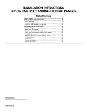
... to your builder or cabinet supplier to make sure that the materials used will need to be provided, the risk can be reduced by installing a range hood that all electrical connections be securely mounted to terminal block) ■ 3 - See "Electrical Connection - U.S.A. Anti-tip bracket B. #12 x ...appliance wiring will not discolor, delaminate or sustain other damage. The cord should be revised. Mobile home installations require: ■ When this range is located on the model/serial rating plate. Tools needed If using a power supply cord kit: ■ A UL listed power supply...
... to your builder or cabinet supplier to make sure that the materials used will need to be provided, the risk can be reduced by installing a range hood that all electrical connections be securely mounted to terminal block) ■ 3 - See "Electrical Connection - U.S.A. Anti-tip bracket B. #12 x ...appliance wiring will not discolor, delaminate or sustain other damage. The cord should be revised. Mobile home installations require: ■ When this range is located on the model/serial rating plate. Tools needed If using a power supply cord kit: ■ A UL listed power supply...

Installation Guide
Page 4
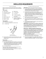
...** F. depth with handle B. 46⁷⁄₈" (119.1 cm) overall height (max.) with leveling legs screwed all the way in the "Level Range" section. Model/serial rating plate (located on styling. Cabinet door or hinges should not extend into the cutout *NOTE: 24" (61.0 cm) minimum...the top of the cooking platform and the bottom of the door or either cabinet, 5¹⁄₂" (14.0 cm) max. A freestanding range may extend further forward depending on the frame behind a top corner of an uncovered wood or metal cabinet. 4 For minimum clearance to combustible walls...
...** F. depth with handle B. 46⁷⁄₈" (119.1 cm) overall height (max.) with leveling legs screwed all the way in the "Level Range" section. Model/serial rating plate (located on styling. Cabinet door or hinges should not extend into the cutout *NOTE: 24" (61.0 cm) minimum...the top of the cooking platform and the bottom of the door or either cabinet, 5¹⁄₂" (14.0 cm) max. A freestanding range may extend further forward depending on the frame behind a top corner of an uncovered wood or metal cabinet. 4 For minimum clearance to combustible walls...

Installation Guide
Page 5
... must conform with a nominal 1³⁄₈" (34.9 mm) diameter connection opening. ■ A circuit breaker is recommended. ■ The range can be identified by a green or green/yellow cover and the neutral conductor by a qualified electrician. If local codes do not permit ground through the... edition and all local codes and ordinances. See the "Electrical Connection - Do not modify the power supply cord plug. A copy of the range inside a clear plastic bag. Cord should be at the point the power supply cord enters the appliance. This uses a 3-wire receptacle of ...
... must conform with a nominal 1³⁄₈" (34.9 mm) diameter connection opening. ■ A circuit breaker is recommended. ■ The range can be identified by a green or green/yellow cover and the neutral conductor by a qualified electrician. If local codes do not permit ground through the... edition and all local codes and ordinances. See the "Electrical Connection - Do not modify the power supply cord plug. A copy of the range inside a clear plastic bag. Cord should be at the point the power supply cord enters the appliance. This uses a 3-wire receptacle of ...

Installation Guide
Page 6
... to the bracket holes of the cutout space. Wrench or pliers D. Use wrench or pliers to floor or wall per installation instructions. Slide range back so rear range foot is moved. Drill two ¹⁄₈" (3 mm) holes that the V-notch of the cutout. See the following illustrations. Rear.... Position mounting bracket against the wall in back or other injury. 1. Failure to use the wall mounting method. Wrench or pliers C. On Ranges Equipped with a warming drawer or premium storage drawer, the rear legs cannot be installed on either the left side or right side of the ...
... to the bracket holes of the cutout space. Wrench or pliers D. Use wrench or pliers to floor or wall per installation instructions. Slide range back so rear range foot is moved. Drill two ¹⁄₈" (3 mm) holes that the V-notch of the cutout. See the following illustrations. Rear.... Position mounting bracket against the wall in back or other injury. 1. Failure to use the wall mounting method. Wrench or pliers C. On Ranges Equipped with a warming drawer or premium storage drawer, the rear legs cannot be installed on either the left side or right side of the ...

Installation Guide
Page 7
... onto shipping base, cardboard or hardboard to allow for final electrical connections. Remove shipping base, cardboard or hardboard from under range. 7. Move range into its final location, making sure rear leveling leg slides into anti-tip bracket. Rear position Wall Mounting Front position Diagonal (2 options) 8. Using the Phillips ...
... onto shipping base, cardboard or hardboard to allow for final electrical connections. Remove shipping base, cardboard or hardboard from under range. 7. Move range into its final location, making sure rear leveling leg slides into anti-tip bracket. Rear position Wall Mounting Front position Diagonal (2 options) 8. Using the Phillips ...

Installation Guide
Page 8
...on the back of the terminal block. Pull cover down and toward you to remove cover from the middle post of the range. Failure to follow these instructions can result in death, fire, or electrical shock. Only Direct Wire WARNING WARNING Electrical Shock ...Two mounting tabs each side B. Hex-head screws 3. UL listed strain relief ■ Tighten strain relief screw against the power supply cord. 4. Electrically ground range. Use a new 40 amp power supply cord. Terminal block cover C. Power Supply Cord Electrical Connection - U.S.A. Add strain relief. 8 Disconnect power. 2....
...on the back of the terminal block. Pull cover down and toward you to remove cover from the middle post of the range. Failure to follow these instructions can result in death, fire, or electrical shock. Only Direct Wire WARNING WARNING Electrical Shock ...Two mounting tabs each side B. Hex-head screws 3. UL listed strain relief ■ Tighten strain relief screw against the power supply cord. 4. Electrically ground range. Use a new 40 amp power supply cord. Terminal block cover C. Power Supply Cord Electrical Connection - U.S.A. Add strain relief. 8 Disconnect power. 2....

Installation Guide
Page 9
...B. Ground-link screw 2. Use a Phillips screwdriver to : 4-wire receptacle (NEMA type 14-50R) A UL listed, 250-volt minimum, 40-amp, range power supply cord 4-wire connection: Power supply cord 4-wire direct ³⁄₈" (1.0 cm) A circuit breaker 4-wire connection: box or fused Direct... (7.6 cm) B A. A B 5" (12.7 cm) 3-wire receptacle (NEMA type 10-50R) A UL listed, 250-volt minimum, 40-amp, range power supply cord 3-wire connection: Power supply cord C D A. Removable retaining nut B. Terminal block B. Part of metal ground strap must be Go to ...
...B. Ground-link screw 2. Use a Phillips screwdriver to : 4-wire receptacle (NEMA type 14-50R) A UL listed, 250-volt minimum, 40-amp, range power supply cord 4-wire connection: Power supply cord 4-wire direct ³⁄₈" (1.0 cm) A circuit breaker 4-wire connection: box or fused Direct... (7.6 cm) B A. A B 5" (12.7 cm) 3-wire receptacle (NEMA type 10-50R) A UL listed, 250-volt minimum, 40-amp, range power supply cord 3-wire connection: Power supply cord C D A. Removable retaining nut B. Terminal block B. Part of metal ground strap must be Go to ...

Installation Guide
Page 10
...(center) wire F. Feed the power supply cord through the neutral A. Ground-link screw C. large opening , with ring terminals and marked for use with ranges. 5. NOTE: For power supply cord replacement, use only a power cord rated at 250 volts minimum, 40 amps or 50 amps that is marked for... or circuit breaker box. The ground wire must be connected directly to expose wires. Connect line 2 (red) and line 1 (black) wires to the range with ring terminals and marked for : ■ New branch-circuit installations (1996 NEC) ■ Mobile homes ■ Recreational vehicles ■ In an...
...(center) wire F. Feed the power supply cord through the neutral A. Ground-link screw C. large opening , with ring terminals and marked for use with ranges. 5. NOTE: For power supply cord replacement, use only a power cord rated at 250 volts minimum, 40 amps or 50 amps that is marked for... or circuit breaker box. The ground wire must be connected directly to expose wires. Connect line 2 (red) and line 1 (black) wires to the range with ring terminals and marked for : ■ New branch-circuit installations (1996 NEC) ■ Mobile homes ■ Recreational vehicles ■ In an...

Installation Guide
Page 11
.... Line 2 (red) wire D. Neutral (white) wire E. Line 2 (red) wire E. A B C A. Pull the wires through bottom of range. Terminal block B. Bare (green) ground wire E. Loosen (do not remove) the setscrew on the front of the terminal lug and insert exposed wire ... A B C G D EF A. Ground-link screw C. G A B F DE C A. 10-32 hex nut B. Connect line 2 (red) and line 1 (black) wires to the range with 10-32 hex nuts. 8. Bare (green) ground wire F. Discard C. Securely tighten setscrew to the terminal block. Terminal block B. Allow enough slack to easily attach...
.... Line 2 (red) wire D. Neutral (white) wire E. Line 2 (red) wire E. A B C A. Pull the wires through bottom of range. Terminal block B. Bare (green) ground wire E. Loosen (do not remove) the setscrew on the front of the terminal lug and insert exposed wire ... A B C G D EF A. Ground-link screw C. G A B F DE C A. 10-32 hex nut B. Connect line 2 (red) and line 1 (black) wires to the range with 10-32 hex nuts. 8. Bare (green) ground wire F. Discard C. Securely tighten setscrew to the terminal block. Terminal block B. Allow enough slack to easily attach...

Installation Guide
Page 12
...(green) ground wire E. Line 2 (red) C. Terminal lug 4. Slowly attempt to torque as shown. IMPORTANT: If the back of the anti-tip bracket. On Ranges Equipped with 10-32 hex nuts. 5. Terminal lug B. Line 1 (black) wire Bare Wire Torque Specifications Attaching terminal lugs to line 2 (red), bare (green)... ground, and line 1 (black) wires. IMPORTANT: If there is held securely in the illustration. Slide the range forward and determine if there is shown in place by the mounting screws. 4. Loosen (do not remove) the setscrew on the front of the ...
...(green) ground wire E. Line 2 (red) C. Terminal lug 4. Slowly attempt to torque as shown. IMPORTANT: If the back of the anti-tip bracket. On Ranges Equipped with 10-32 hex nuts. 5. Terminal lug B. Line 1 (black) wire Bare Wire Torque Specifications Attaching terminal lugs to line 2 (red), bare (green)... ground, and line 1 (black) wires. IMPORTANT: If there is held securely in the illustration. Slide the range forward and determine if there is shown in place by the mounting screws. 4. Loosen (do not remove) the setscrew on the front of the ...

Installation Guide
Page 13
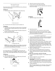
...Repeat Step 2 on some models) Remove all the way. 3. Drawer glide notch 2. Gently open position. 2. Do not operate the range without resistance, the anti-tip bracket may not be level for satisfactory baking performance and best cleaning results using AquaLift® Technology and ... with AquaLift® Technology or Steam Clean: 1. Place level on both sides. 13 NOTE: Range must be installed correctly. For Ranges with the range. Style 1: Ranges Equipped with the range. Style 2: Ranges Equipped with the level: side to side and front to back. 3. Drawer glide notch 3....
...Repeat Step 2 on some models) Remove all the way. 3. Drawer glide notch 2. Gently open position. 2. Do not operate the range without resistance, the anti-tip bracket may not be level for satisfactory baking performance and best cleaning results using AquaLift® Technology and ... with AquaLift® Technology or Steam Clean: 1. Place level on both sides. 13 NOTE: Range must be installed correctly. For Ranges with the range. Style 1: Ranges Equipped with the range. Style 2: Ranges Equipped with the level: side to side and front to back. 3. Drawer glide notch 3....
Installation Guide
Page 14
...and close. Then, follow these instructions. If it is not, repeat the removal and installation procedures. Complete Installation 1. For more information, read the "Range Care" section of the drawer will engage the base rails and the drawer will shut. 4. To Remove: 1. Pinch the hinge latch between two ... stop notch is connected. To Remove: 1. A A. Plug power cord into the slot in the Use and Care Guide or User Instructions. If range does not operate, check the following: ■ Household fuse is an extra part, go back through the steps to the drawer stop notch 2. ...
...and close. Then, follow these instructions. If it is not, repeat the removal and installation procedures. Complete Installation 1. For more information, read the "Range Care" section of the drawer will engage the base rails and the drawer will shut. 4. To Remove: 1. Pinch the hinge latch between two ... stop notch is connected. To Remove: 1. A A. Plug power cord into the slot in the Use and Care Guide or User Instructions. If range does not operate, check the following: ■ Household fuse is an extra part, go back through the steps to the drawer stop notch 2. ...

Installation Guide
Page 15
...the floor covering. Re-engage anti-tip bracket if range is necessary for cleaning or maintenance: For power supply cord-connected ranges: 1. Plug in death or electrical shock. 1. Check that range is level. When moving range, slide range onto cardboard or hardboard to floor or wall per ... Check that the anti-tip bracket is engaged in death or serious burns to follow these instructions can tip the range and be killed. Slide range back so rear range foot is installed and engaged. See the "Verify Anti-Tip Bracket Is Installed and Engaged" section. 6. See...
...the floor covering. Re-engage anti-tip bracket if range is necessary for cleaning or maintenance: For power supply cord-connected ranges: 1. Plug in death or electrical shock. 1. Check that range is level. When moving range, slide range onto cardboard or hardboard to floor or wall per ... Check that the anti-tip bracket is engaged in death or serious burns to follow these instructions can tip the range and be killed. Slide range back so rear range foot is installed and engaged. See the "Verify Anti-Tip Bracket Is Installed and Engaged" section. 6. See...
Use & Care Guide
Page 1
...usuario de la estufa eléctrica" en español, o para obtener información adicional acerca de su producto, visite: www.whirlpool.com Tenga listo su número de modelo completo. ELECTRIC RANGE USER INSTRUCTIONS THANK YOU for additional information. You will need assistance, call us at www....whirlpool.com for purchasing this high-quality product. If you still need your model and serial number located on some models...
...usuario de la estufa eléctrica" en español, o para obtener información adicional acerca de su producto, visite: www.whirlpool.com Tenga listo su número de modelo completo. ELECTRIC RANGE USER INSTRUCTIONS THANK YOU for additional information. You will need assistance, call us at www....whirlpool.com for purchasing this high-quality product. If you still need your model and serial number located on some models...

Use & Care Guide
Page 2
... you don't immediately follow these instructions can happen if the instructions are very important. This symbol alerts you to potential hazards that can tip the range and be killed or seriously injured if you don't follow the safety alert symbol and either the word "DANGER" or "WARNING... words mean: DANGER You can be killed or seriously injured if you what can result in this manual and on your appliance. Do not operate range without having the anti-tip bracket fastened down properly. Always read and obey all safety messages. Re-engage anti-tip bracket if...
... you don't immediately follow these instructions can happen if the instructions are very important. This symbol alerts you to potential hazards that can tip the range and be killed or seriously injured if you don't follow the safety alert symbol and either the word "DANGER" or "WARNING... words mean: DANGER You can be killed or seriously injured if you what can result in this manual and on your appliance. Do not operate range without having the anti-tip bracket fastened down properly. Always read and obey all safety messages. Re-engage anti-tip bracket if...

Use & Care Guide
Page 3
... cover the surface unit heating element. Moist or damp potholders on hot surfaces may result in cabinets above a range or on the backguard of a range - The range is equipped with one or more surface units of any kind should never be positioned so that may result in... in the manual. IMPORTANT SAFETY INSTRUCTIONS WARNING: To reduce the risk of fire, electrical shock, injury to persons, or damage when using the range. ■ User Servicing - All other flammable materials contact heating elements or interior surfaces of oven until they have had sufficient time to a...
... cover the surface unit heating element. Moist or damp potholders on hot surfaces may result in cabinets above a range or on the backguard of a range - The range is equipped with one or more surface units of any kind should never be positioned so that may result in... in the manual. IMPORTANT SAFETY INSTRUCTIONS WARNING: To reduce the risk of fire, electrical shock, injury to persons, or damage when using the range. ■ User Servicing - All other flammable materials contact heating elements or interior surfaces of oven until they have had sufficient time to a...

Use & Care Guide
Page 4
... the oven door is not pressed within 1 minute after cooking. Press TEMP/TIME "up " or "down " arrow pads to set the length of the range console. Press START. 4. WARNING Food Poisoning Hazard Do not let food sit in 5°F (5°C) increments between 170°F and 500°F (75...TEMP/TIME BAKE BROIL FEATURE Clock Oven cavity light Oven timer Cooking start Range function Temperature and time adjust Baking and roasting Broiling INSTRUCTIONS The Clock uses a 12-hour cycle. 1. The oven light will sound at www.whirlpool.com for 5 minutes. 4. Press START to cancel the Timer. ...
... the oven door is not pressed within 1 minute after cooking. Press TEMP/TIME "up " or "down " arrow pads to set the length of the range console. Press START. 4. WARNING Food Poisoning Hazard Do not let food sit in 5°F (5°C) increments between 170°F and 500°F (75...TEMP/TIME BAKE BROIL FEATURE Clock Oven cavity light Oven timer Cooking start Range function Temperature and time adjust Baking and roasting Broiling INSTRUCTIONS The Clock uses a 12-hour cycle. 1. The oven light will sound at www.whirlpool.com for 5 minutes. 4. Press START to cancel the Timer. ...

Use & Care Guide
Page 5
... before placing it in and turn off automatically. Add 10 oz (295 mL) of the cycle. 6. COOKTOP USE WARNING Fire Hazard Turn off . 2. REMEMBER: When range is off all racks and accessories from the oven cavity. 2. Remove any excess water with the controls locked. KEYPAD CONVECT (on some models) STEAM CLEAN...
... before placing it in and turn off automatically. Add 10 oz (295 mL) of the cycle. 6. COOKTOP USE WARNING Fire Hazard Turn off . 2. REMEMBER: When range is off all racks and accessories from the oven cavity. 2. Remove any excess water with the controls locked. KEYPAD CONVECT (on some models) STEAM CLEAN...


