Use & Care Guide
Page 1
..." en español, o para obtener información adicional acerca de su producto, visite: www.whirlpool.com Tenga listo su número de modelo completo. If you still need your model and serial number...located on some models 11 General Cleaning 12 Oven Light 13 TROUBLESHOOTING 13 ACCESSORIES 15 WARRANTY 15 W10394383A Table of Contents RANGE SAFETY 2 The Anti-Tip Bracket 2 FEATURE GUIDE 4 COOKTOP USE 5 Cookware 7 Home Canning 7 OVEN USE 8 ... detrás del panel del cajón de almacenamiento. ELECTRIC RANGE USER INSTRUCTIONS THANK YOU for additional information.
..." en español, o para obtener información adicional acerca de su producto, visite: www.whirlpool.com Tenga listo su número de modelo completo. If you still need your model and serial number...located on some models 11 General Cleaning 12 Oven Light 13 TROUBLESHOOTING 13 ACCESSORIES 15 WARRANTY 15 W10394383A Table of Contents RANGE SAFETY 2 The Anti-Tip Bracket 2 FEATURE GUIDE 4 COOKTOP USE 5 Cookware 7 Home Canning 7 OVEN USE 8 ... detrás del panel del cajón de almacenamiento. ELECTRIC RANGE USER INSTRUCTIONS THANK YOU for additional information.
Use & Care Guide
Page 3
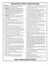
...All other flammable materials contact heating elements or interior surfaces of electric shock. To reduce the risk of burns, ignition of flammable materials, and spillage due to persons, or damage when using the range. ■ User Servicing - Improper installation of these openings, ... in injury. ■ Keep Oven Vent Ducts Unobstructed. ■ Placement of fire, electrical shock, injury to unintentional contact with ventilating hood - ■ Clean Ventilating Hoods Frequently - For self-cleaning ranges - ■ Do Not Clean Door Gasket - Smother fire or flame or use ...
...All other flammable materials contact heating elements or interior surfaces of electric shock. To reduce the risk of burns, ignition of flammable materials, and spillage due to persons, or damage when using the range. ■ User Servicing - Improper installation of these openings, ... in injury. ■ Keep Oven Vent Ducts Unobstructed. ■ Placement of fire, electrical shock, injury to unintentional contact with ventilating hood - ■ Clean Ventilating Hoods Frequently - For self-cleaning ranges - ■ Do Not Clean Door Gasket - Smother fire or flame or use ...
Use & Care Guide
Page 13
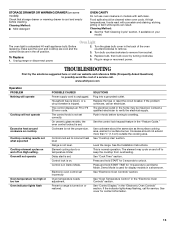
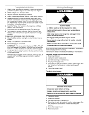
...DRAWER OR WARMING DRAWER (on some models) Check that storage drawer or warming drawer is cool and empty before turning to a setting. The electrical outlet in the off position. 2. Before replacing, make sure the oven and cooktop are cool and the control knobs are in the home ...." Press and hold START TIME for display models in the "Electronic Oven Controls" section. Turn the glass bulb cover in range or reconnect power. www.whirlpool.com Operation PROBLEM Nothing will operate Cooktop will not operate Oven temperature too high or too low Oven indicator lights flash POSSIBLE ...
...DRAWER OR WARMING DRAWER (on some models) Check that storage drawer or warming drawer is cool and empty before turning to a setting. The electrical outlet in the off position. 2. Before replacing, make sure the oven and cooktop are cool and the control knobs are in the home ...." Press and hold START TIME for display models in the "Electronic Oven Controls" section. Turn the glass bulb cover in range or reconnect power. www.whirlpool.com Operation PROBLEM Nothing will operate Cooktop will not operate Oven temperature too high or too low Oven indicator lights flash POSSIBLE ...
Dimension Guide
Page 1
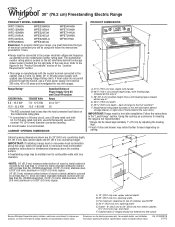
...combination above the cooktop surface. E F Because Whirlpool Corporation policy includes a continuous commitment to improve our products, we reserve the right to top of frame behind the oven door) IMPORTANT: Range must be level after installation. For minimum clearance ... hinges should not extend into the cutout Dimensions are for use with product. q Range must be connected to the cabinet. 30" (76.2 cm) Freestanding Electric Range PRODUCT MODEL NUMBERS WFC110M0A WFE330W0A WFE540H0A WFC120M0A WFE510S0A WFE710H0A WFC130M0A WFE520C0A WFE714HLA WFC310S0A WFE524CLA WFE720H0A...
...combination above the cooktop surface. E F Because Whirlpool Corporation policy includes a continuous commitment to improve our products, we reserve the right to top of frame behind the oven door) IMPORTANT: Range must be level after installation. For minimum clearance ... hinges should not extend into the cutout Dimensions are for use with product. q Range must be connected to the cabinet. 30" (76.2 cm) Freestanding Electric Range PRODUCT MODEL NUMBERS WFC110M0A WFE330W0A WFE540H0A WFC120M0A WFE510S0A WFE710H0A WFC130M0A WFE520C0A WFE714HLA WFC310S0A WFE524CLA WFE720H0A...
Installation Guide
Page 1
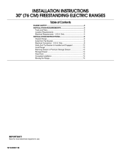
U.S.A. U.S.A. Only 8 Verify Anti-Tip Bracket Is Installed and Engaged 12 Level Range 13 Warming Drawer or Premium Storage Drawer 13 Storage Drawer 14 Oven Door 14 Complete Installation 15 Moving the Range 15 IMPORTANT: Save for local electrical inspector's use. Only 5 INSTALLATION INSTRUCTIONS 6 Unpack Range 6 Install Anti-Tip Bracket 6 Electrical Connection - W10403811B INSTALLATION INSTRUCTIONS 30" (76 CM) FREESTANDING ELECTRIC RANGES Table of Contents RANGE SAFETY 2 INSTALLATION REQUIREMENTS 3 Tools and Parts 3 Location Requirements 3 Electrical Requirements -
U.S.A. U.S.A. Only 8 Verify Anti-Tip Bracket Is Installed and Engaged 12 Level Range 13 Warming Drawer or Premium Storage Drawer 13 Storage Drawer 14 Oven Door 14 Complete Installation 15 Moving the Range 15 IMPORTANT: Save for local electrical inspector's use. Only 5 INSTALLATION INSTRUCTIONS 6 Unpack Range 6 Install Anti-Tip Bracket 6 Electrical Connection - W10403811B INSTALLATION INSTRUCTIONS 30" (76 CM) FREESTANDING ELECTRIC RANGES Table of Contents RANGE SAFETY 2 INSTALLATION REQUIREMENTS 3 Tools and Parts 3 Location Requirements 3 Electrical Requirements -
Installation Guide
Page 3
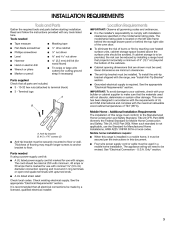
..., use with nominal 1³⁄₈" (3.5 cm) diameter connection opening dimensions that all electrical connections be made by installing a range hood that projects horizontally a minimum of 5" (12.7 cm) beyond the bottom of UL and CSA International and complies with ranges. Terminal lugs A B A. This oven has been designed in ring terminals or open-end...
..., use with nominal 1³⁄₈" (3.5 cm) diameter connection opening dimensions that all electrical connections be made by installing a range hood that projects horizontally a minimum of 5" (12.7 cm) beyond the bottom of UL and CSA International and complies with ranges. Terminal lugs A B A. This oven has been designed in ring terminals or open-end...
Installation Guide
Page 5
...conform with the rating of the oven door. The fourth (grounding) conductor must determine the type of electrical connection you must be provided at each end of the range inside a clear plastic bag. For 50-amp rated cord kits, use kits that the ground path... and wire gauge are in accordance with local codes. ■ The Tech Sheet is manufactured with ranges. Electrical Requirements - See "Electrical Connection - Only" section. Use a 3-wire, UL listed, 40- U.S.A. Only" section. 3-wire receptacle (10-50R) ■ Allow 2 to 3 ft ...
...conform with the rating of the oven door. The fourth (grounding) conductor must determine the type of electrical connection you must be provided at each end of the range inside a clear plastic bag. For 50-amp rated cord kits, use kits that the ground path... and wire gauge are in accordance with local codes. ■ The Tech Sheet is manufactured with ranges. Electrical Requirements - See "Electrical Connection - Only" section. Use a 3-wire, UL listed, 40- U.S.A. Only" section. 3-wire receptacle (10-50R) ■ Allow 2 to 3 ft ...

Installation Guide
Page 7
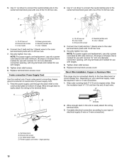
...;" (3 mm) holes that the V-notch of the cutout space. Remove shipping base, cardboard or hardboard from centerline as shown. Move range into its final location, making sure rear leveling leg slides into anti-tip bracket. 8. Position mounting bracket against the wall in the ...or floor with the two #12 x 1⁵⁄₈" screws provided. 6. Floor Mounting 5. Move range forward onto shipping base, cardboard or hardboard to allow for final electrical connections. Using the Phillips screwdriver, mount anti-tip bracket to the bracket holes of the cutout. Determine...
...;" (3 mm) holes that the V-notch of the cutout space. Remove shipping base, cardboard or hardboard from centerline as shown. Move range into its final location, making sure rear leveling leg slides into anti-tip bracket. 8. Position mounting bracket against the wall in the ...or floor with the two #12 x 1⁵⁄₈" screws provided. 6. Floor Mounting 5. Move range forward onto shipping base, cardboard or hardboard to allow for final electrical connections. Using the Phillips screwdriver, mount anti-tip bracket to the bracket holes of the cutout. Determine...
Installation Guide
Page 8
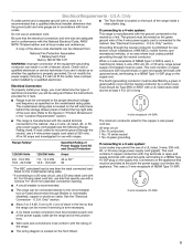
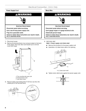
...each side B. Hex-head screws 3. Remove plastic tag holding three 10-32 hex nuts from range. 4. Use a new 40 amp power supply cord. Electrical Shock Hazard Disconnect power before servicing. Electrically ground range. Disconnect power. 2. Terminal block cover C. Failure to follow these instructions can result in the... wire. Failure to follow these instructions can result in death, fire, or electrical shock. U.S.A. Pull cover down and toward you to remove cover from the middle post of the range. Add strain relief. Plug into a grounded outlet. UL listed strain relief...
...each side B. Hex-head screws 3. Remove plastic tag holding three 10-32 hex nuts from range. 4. Use a new 40 amp power supply cord. Electrical Shock Hazard Disconnect power before servicing. Electrically ground range. Disconnect power. 2. Terminal block cover C. Failure to follow these instructions can result in the... wire. Failure to follow these instructions can result in death, fire, or electrical shock. U.S.A. Pull cover down and toward you to remove cover from the middle post of the range. Add strain relief. Plug into a grounded outlet. UL listed strain relief...

Installation Guide
Page 9
...Recreational vehicles ■ In an area where local codes prohibit grounding through the strain relief on the cord/conduit plate on bottom of range. Conduit ■ Tighten strain relief screw against the flexible conduit. 5. Feed the power supply cord through the neutral 1. A ...wires 4. Complete installation following instructions for your type of electrical connection: 4-wire (recommended) 3-wire (if 4-wire is not available) Electrical Connection Options If your home has: And you will be Go to Section: connecting to the range with the ground-link screw and ground-link section. ...
...Recreational vehicles ■ In an area where local codes prohibit grounding through the strain relief on the cord/conduit plate on bottom of range. Conduit ■ Tighten strain relief screw against the flexible conduit. 5. Feed the power supply cord through the neutral 1. A ...wires 4. Complete installation following instructions for your type of electrical connection: 4-wire (recommended) 3-wire (if 4-wire is not available) Electrical Connection Options If your home has: And you will be Go to Section: connecting to the range with the ground-link screw and ground-link section. ...
Installation Guide
Page 10
... wires to the center terminal block post with ranges. 5. NOTE: For power supply cord replacement, use only a power cord rated at 250 volts minimum, 40 amps or 50 amps that is marked for use with one of electrical supply (4-wire or 3-wire connection). Replace terminal ... strain relief screws. 6. Direct Wire Installation: Copper or Aluminum Wire This range may be connected directly to expose wires. Strip outer covering back 3" (7.6 cm) to the fuse disconnect or circuit breaker box. Complete electrical connection according to the outer terminal block posts with 10-32 hex nuts....
... wires to the center terminal block post with ranges. 5. NOTE: For power supply cord replacement, use only a power cord rated at 250 volts minimum, 40 amps or 50 amps that is marked for use with one of electrical supply (4-wire or 3-wire connection). Replace terminal ... strain relief screws. 6. Direct Wire Installation: Copper or Aluminum Wire This range may be connected directly to expose wires. Strip outer covering back 3" (7.6 cm) to the fuse disconnect or circuit breaker box. Complete electrical connection according to the outer terminal block posts with 10-32 hex nuts....
Installation Guide
Page 15
... is necessary for heat. See the "Verify Anti-Tip Bracket Is Installed and Engaged" section. 6. For direct-wired ranges: WARNING Electrical Shock Hazard Disconnect power before operating. Plug in the range Use and Care Guide or User Instructions. 7. Install anti-tip bracket to avoid damaging the floor covering. If there is cold, turn...
... is necessary for heat. See the "Verify Anti-Tip Bracket Is Installed and Engaged" section. 6. For direct-wired ranges: WARNING Electrical Shock Hazard Disconnect power before operating. Plug in the range Use and Care Guide or User Instructions. 7. Install anti-tip bracket to avoid damaging the floor covering. If there is cold, turn...


