

Dimension Guide
Page 1
... W10252706A 1/04/10 30" (76 cm) Freestanding Electric Range PRODUCT MODEL NUMBERS GFE461LV GFE471LV WFE301LV WFE361LV WFE364LV WFE366LV WFE371LV WFE374LV WFE381LV WFE114LW WFE115LX RF110AXS RF111PXS RF114PXS RF212PXS RF263LXT RF264LXS Electrical: Range must be connected directly to the circuit breaker box (or... with leveling legs screwed all the way in* C. 36" (91.4 cm) cooktop height (max.) with ranges. Outlet - 8" (20.3 cm) to change without notice. Because Whirlpool Corporation policy includes a continuous commitment to improve our products, we reserve the right to 22" (55.9 cm...
... W10252706A 1/04/10 30" (76 cm) Freestanding Electric Range PRODUCT MODEL NUMBERS GFE461LV GFE471LV WFE301LV WFE361LV WFE364LV WFE366LV WFE371LV WFE374LV WFE381LV WFE114LW WFE115LX RF110AXS RF111PXS RF114PXS RF212PXS RF263LXT RF264LXS Electrical: Range must be connected directly to the circuit breaker box (or... with leveling legs screwed all the way in* C. 36" (91.4 cm) cooktop height (max.) with ranges. Outlet - 8" (20.3 cm) to change without notice. Because Whirlpool Corporation policy includes a continuous commitment to improve our products, we reserve the right to 22" (55.9 cm...

Installation Instructions
Page 1
U.S.A. U.S.A. Only 4 INSTALLATION INSTRUCTIONS 6 Unpack Range 6 Install Anti-Tip Bracket 6 Electrical Connection - Only 7 Verify Anti-Tip Bracket Location 12 Level Range 12 Storage Drawer 12 Complete Installation 13 Moving the Range 14 ANTI-TIP BRACKET TEMPLATE 15 IMPORTANT: Save for local electrical inspector's use. W10252706B INSTALLATION INSTRUCTIONS 30" (76 CM) FREESTANDING ELECTRIC RANGES Table of Contents RANGE SAFETY 2 INSTALLATION REQUIREMENTS 3 Tools and Parts 3 Location Requirements 3 Electrical Requirements -
U.S.A. U.S.A. Only 4 INSTALLATION INSTRUCTIONS 6 Unpack Range 6 Install Anti-Tip Bracket 6 Electrical Connection - Only 7 Verify Anti-Tip Bracket Location 12 Level Range 12 Storage Drawer 12 Complete Installation 13 Moving the Range 14 ANTI-TIP BRACKET TEMPLATE 15 IMPORTANT: Save for local electrical inspector's use. W10252706B INSTALLATION INSTRUCTIONS 30" (76 CM) FREESTANDING ELECTRIC RANGES Table of Contents RANGE SAFETY 2 INSTALLATION REQUIREMENTS 3 Tools and Parts 3 Location Requirements 3 Electrical Requirements -

Installation Instructions
Page 2
...safety alert symbol and either the word "DANGER" or "WARNING." This is moved. WARNING Tip Over Hazard A child or adult can tip the range and be killed or seriously injured if you and others are not followed. WARNING You can be killed. Connect anti-tip bracket to potential hazards... that can kill or hurt you don't follow instructions. Reconnect the anti-tip bracket, if the range is the safety alert symbol. We have provided many important safety messages in death or serious burns to reduce the chance of others . These ...
...safety alert symbol and either the word "DANGER" or "WARNING." This is moved. WARNING Tip Over Hazard A child or adult can tip the range and be killed or seriously injured if you and others are not followed. WARNING You can be killed. Connect anti-tip bracket to potential hazards... that can kill or hurt you don't follow instructions. Reconnect the anti-tip bracket, if the range is the safety alert symbol. We have provided many important safety messages in death or serious burns to reduce the chance of others . These ...

Installation Instructions
Page 3
... installation. To install the antitip bracket shipped with the maximum allowable wood cabinet temperatures of UL and CSA International and complies with the range, see "Install Anti-Tip Bracket" section. ■ Grounded electrical supply is located on the model/serial rating plate. Mobile home ...installations require: ■ When this range must be installed. This oven has been designed in the kitchen. ■ To eliminate the risk of flooring may require longer screws...
... installation. To install the antitip bracket shipped with the maximum allowable wood cabinet temperatures of UL and CSA International and complies with the range, see "Install Anti-Tip Bracket" section. ■ Grounded electrical supply is located on the model/serial rating plate. Mobile home ...installations require: ■ When this range must be installed. This oven has been designed in the kitchen. ■ To eliminate the risk of flooring may require longer screws...

Installation Instructions
Page 4
...cooktop surface. Do not use an extension cord. A copy of wood or metal cabinet is properly grounded. D. 30¹⁄₈" (76.5 cm) min. A freestanding range may be raised approximately 1" (2.5 cm) by adjusting the leveling legs. A. 13" (33.0 cm) max. upper cabinet depth B. 30" (76.2 cm) min. ... (max.) with leveling legs screwed all local codes and ordinances. Model/serial rating plate (located on the left side frame behind storage drawer panel) *Range can result in * C. 36" (91.4 cm) cooktop height (max.) with leveling legs screwed all the way in a risk of an uncovered...
...cooktop surface. Do not use an extension cord. A copy of wood or metal cabinet is properly grounded. D. 30¹⁄₈" (76.5 cm) min. A freestanding range may be raised approximately 1" (2.5 cm) by adjusting the leveling legs. A. 13" (33.0 cm) max. upper cabinet depth B. 30" (76.2 cm) min. ... (max.) with leveling legs screwed all local codes and ordinances. Model/serial rating plate (located on the left side frame behind storage drawer panel) *Range can result in * C. 36" (91.4 cm) cooktop height (max.) with leveling legs screwed all the way in a risk of an uncovered...

Installation Instructions
Page 5
...white cover. The ground must be revised so the green ground wire of the 4-wire power supply cord is located on the back of the range or inside the storage drawer in a clear plastic bag. The fourth (grounding) conductor must be provided at the junction box). ■ ...Wire sizes and connections must conform with ranges. Refer to the circuit breaker box (or fused disconnect) through the neutral, use a 4-wire power supply cord rated at least 4 ft (1.22 m) ...
...white cover. The ground must be revised so the green ground wire of the 4-wire power supply cord is located on the back of the range or inside the storage drawer in a clear plastic bag. The fourth (grounding) conductor must be provided at the junction box). ■ ...Wire sizes and connections must conform with ranges. Refer to the circuit breaker box (or fused disconnect) through the neutral, use a 4-wire power supply cord rated at least 4 ft (1.22 m) ...

Installation Instructions
Page 6
.... See the "Storage Drawer" section. A D C Install Anti-Tip Bracket WARNING Tip Over Hazard A child or adult can tip the range and be necessary to do so can result in cabinet opening so that the left edge is against cabinet and top edge is against rear...half turn. A. Wrench or pliers 6 Use a ¼" drive ratchet to children and adults. Front leveling leg On Ranges Equipped with Warming Drawers: On ranges equipped with overhang. Before moving range, slide range onto shipping base, cardboard or hardboard. 1. Tape template into place. 4. Rear leveling leg C. Use wrench or pliers...
.... See the "Storage Drawer" section. A D C Install Anti-Tip Bracket WARNING Tip Over Hazard A child or adult can tip the range and be necessary to do so can result in cabinet opening so that the left edge is against cabinet and top edge is against rear...half turn. A. Wrench or pliers 6 Use a ¼" drive ratchet to children and adults. Front leveling leg On Ranges Equipped with Warming Drawers: On ranges equipped with overhang. Before moving range, slide range onto shipping base, cardboard or hardboard. 1. Tape template into place. 4. Rear leveling leg C. Use wrench or pliers...

Installation Instructions
Page 7
... (3.2 mm) holes at the positions marked on the bracket template. Remove template from the middle post of the terminal block. Electrically ground range. Two mounting tabs each side B. Electrical Shock Hazard Disconnect power before servicing. A B C A. Hex-head screws 7 Use 8 gauge ...copper or 6 gauge aluminum wire. Disconnect power. 2. Remove the terminal block cover screws located on the thickness of the range. 5. Terminal block cover C. Plug into holes with screws provided. To mount anti-tip bracket to remove cover from floor. Only Power...
... (3.2 mm) holes at the positions marked on the bracket template. Remove template from the middle post of the terminal block. Electrically ground range. Two mounting tabs each side B. Electrical Shock Hazard Disconnect power before servicing. A B C A. Hex-head screws 7 Use 8 gauge ...copper or 6 gauge aluminum wire. Disconnect power. 2. Remove the terminal block cover screws located on the thickness of the range. 5. Terminal block cover C. Plug into holes with screws provided. To mount anti-tip bracket to remove cover from floor. Only Power...

Installation Instructions
Page 8
...A B C 5. Discard C. Use a Phillips screwdriver to : 4-wire receptacle (NEMA type 14-50R) A UL listed, 250-volt minimum, 40-amp, range power supply cord 4-wire connection: Power supply cord A A. Metal ground strap B. UL listed strain relief ■ Tighten strain relief screw against the flexible conduit....box or fused Direct wire disconnect 5" (12.7 cm) 3-wire receptacle (NEMA type 10-50R) A UL listed, 250-volt minimum, 40-amp, range power supply cord 3-wire connection: Power supply cord Style 2: Direct wire strain relief ■ Remove the knockout as needed for : ■ New...
...A B C 5. Discard C. Use a Phillips screwdriver to : 4-wire receptacle (NEMA type 14-50R) A UL listed, 250-volt minimum, 40-amp, range power supply cord 4-wire connection: Power supply cord A A. Metal ground strap B. UL listed strain relief ■ Tighten strain relief screw against the flexible conduit....box or fused Direct wire disconnect 5" (12.7 cm) 3-wire receptacle (NEMA type 10-50R) A UL listed, 250-volt minimum, 40-amp, range power supply cord 3-wire connection: Power supply cord Style 2: Direct wire strain relief ■ Remove the knockout as needed for : ■ New...

Installation Instructions
Page 9
... easily attach the wiring to the terminal block. Feed the power supply cord through the strain relief on the cord/conduit plate on bottom of range. Terminal block B. Ground-link screw C. Line 1 (black) 6. Tighten strain relief screws. 9. Ground-link screw D. Securely tighten hex nuts. C D A. Power...the ground-link screw and ground-link section. Use ³⁄₈" nut driver to connect the neutral (white) wire to the range with one of power supply cord. 1. Replace terminal block access cover. 9 Allow enough slack to easily attach the wiring to the ...
... easily attach the wiring to the terminal block. Feed the power supply cord through the strain relief on the cord/conduit plate on bottom of range. Terminal block B. Ground-link screw C. Line 1 (black) 6. Tighten strain relief screws. 9. Ground-link screw D. Securely tighten hex nuts. C D A. Power...the ground-link screw and ground-link section. Use ³⁄₈" nut driver to connect the neutral (white) wire to the range with one of power supply cord. 1. Replace terminal block access cover. 9 Allow enough slack to easily attach the wiring to the ...

Installation Instructions
Page 10
... lug and insert exposed wire end through the neutral 1. Strip the insulation back ³⁄₈" (1.0 cm) from the back of the range. Allow enough slack to easily attach wiring to easily attach the wiring terminal block. 3. Bare (green) ground wire E. Ground-link screw C.... A A B B C A. Neutral (white) wire E. Direct Wire Installation: Copper or Aluminum Wire This range may be connected directly to remove the ground-link screw from the end of terminal lugs. Use a Phillips screwdriver to the fuse disconnect or...
... lug and insert exposed wire end through the neutral 1. Strip the insulation back ³⁄₈" (1.0 cm) from the back of the range. Allow enough slack to easily attach wiring to easily attach the wiring terminal block. 3. Bare (green) ground wire E. Ground-link screw C.... A A B B C A. Neutral (white) wire E. Direct Wire Installation: Copper or Aluminum Wire This range may be connected directly to remove the ground-link screw from the end of terminal lugs. Use a Phillips screwdriver to the fuse disconnect or...

Installation Instructions
Page 11
...) C. Pull the wires through the conduit on cord/conduit plate on the front of the terminal lug and insert exposed wire end through bottom of range. A B C 2. Attach terminal lugs to the terminal block. Securely tighten setscrew to the outer terminal block posts with 10-32 hex nuts. 5. Ground-link screw C. Line...
...) C. Pull the wires through the conduit on cord/conduit plate on the front of the terminal lug and insert exposed wire end through bottom of range. A B C 2. Attach terminal lugs to the terminal block. Securely tighten setscrew to the outer terminal block posts with 10-32 hex nuts. 5. Ground-link screw C. Line...

Installation Instructions
Page 12
.... Replace the storage drawer (on rack and check levelness of the storage drawer, placing the screwdriver tip on the storage drawer until the range is level. Drawer clip 3. view from the anti-tip bracket. Verify Anti-Tip Bracket Location 1. See the "Storage Drawer" section. ...To Remove: 1. Push the drawer back approximately 1" (2.5 cm). Place level on some models). If range is not level, pull range forward until the range is level. Repeat steps 2, 3, and 4, for removal. Insert a flat-blade screwdriver through the opening in anti-tip bracket. ...
.... Replace the storage drawer (on rack and check levelness of the storage drawer, placing the screwdriver tip on the storage drawer until the range is level. Drawer clip 3. view from the anti-tip bracket. Verify Anti-Tip Bracket Location 1. See the "Storage Drawer" section. ...To Remove: 1. Push the drawer back approximately 1" (2.5 cm). Place level on some models). If range is not level, pull range forward until the range is level. Repeat steps 2, 3, and 4, for removal. Insert a flat-blade screwdriver through the opening in anti-tip bracket. ...

Installation Instructions
Page 13
...parts are removing and replacing the storage drawer, a slight push may be needed to a level position. 3. Dry thoroughly with the gap in the range Use and Care Guide. 7. Slowly push the storage drawer into an outlet. ■ Electrical supply is intact and tight; Dispose of liquid household ...cleaner and warm water to see which step was skipped. 2. Read "Range Use" in the drawer glides. Plug power cord into the closed position. 5. Turn power on surface burners and oven. or circuit breaker has...
...parts are removing and replacing the storage drawer, a slight push may be needed to a level position. 3. Dry thoroughly with the gap in the range Use and Care Guide. 7. Slowly push the storage drawer into an outlet. ■ Electrical supply is intact and tight; Dispose of liquid household ...cleaner and warm water to see which step was skipped. 2. Read "Range Use" in the drawer glides. Plug power cord into the closed position. 5. Turn power on surface burners and oven. or circuit breaker has...

Installation Instructions
Page 14
...that anti-tip bracket is installed: ■ Look for the anti-tip bracket securely attached to floor. ■ Slide range back so rear range foot is level. 6. Replace all parts and panels before servicing. Disconnect power. 2. Reconnect power. 6. Check that anti... bracket securely attached to floor. ■ Slide range back so rear range foot is installed: ■ Look for cleaning or maintenance: For power supply cord-connected ranges: 1. Complete cleaning or maintenance. 4. Slide range forward. 2. Slide range forward. 3. Connect anti-tip bracket to avoid damaging...
...that anti-tip bracket is installed: ■ Look for the anti-tip bracket securely attached to floor. ■ Slide range back so rear range foot is level. 6. Replace all parts and panels before servicing. Disconnect power. 2. Reconnect power. 6. Check that anti... bracket securely attached to floor. ■ Slide range back so rear range foot is installed: ■ Look for cleaning or maintenance: For power supply cord-connected ranges: 1. Complete cleaning or maintenance. 4. Slide range forward. 2. Slide range forward. 3. Connect anti-tip bracket to avoid damaging...

Owners Manual
Page 1
..., call us at www.whirlpool.com for purchasing this high-quality product. Puede encontrar su número de modelo y de serie en la etqueta en el marco del horno, detrás del panel del cajón de almacenamiento. Table of Contents RANGE SAFETY 2 The Anti-Tip... 6 Positioning Racks and Bakeware 7 Oven Vent 7 Baking and Roasting 7 Broiling 7 Convection Baking and Roasting 8 Timed Cooking (on some models 8 RANGE CARE 8 Self-Cleaning Cycle (on some models 9 General Cleaning 9 Oven Light 10 TROUBLESHOOTING 10 ACCESSORIES 11 WARRANTY 12 W10200357B ® ELECTRIC...
..., call us at www.whirlpool.com for purchasing this high-quality product. Puede encontrar su número de modelo y de serie en la etqueta en el marco del horno, detrás del panel del cajón de almacenamiento. Table of Contents RANGE SAFETY 2 The Anti-Tip... 6 Positioning Racks and Bakeware 7 Oven Vent 7 Baking and Roasting 7 Broiling 7 Convection Baking and Roasting 8 Timed Cooking (on some models 8 RANGE CARE 8 Self-Cleaning Cycle (on some models 9 General Cleaning 9 Oven Light 10 TROUBLESHOOTING 10 ACCESSORIES 11 WARRANTY 12 W10200357B ® ELECTRIC...
Owners Manual
Page 2
...you to reduce the chance of injury, and tell you what can result in this manual and on your appliance. However, the range can tip if you don't immediately follow these instructions can happen if the instructions are very important. See the installation instructions for ...safety alert symbol and either the word "DANGER" or "WARNING." Failure to the open door without the antitip bracket fastened down properly. RANGE SAFETY Your safety and the safety of others . The California Safe Drinking Water and Toxic Enforcement Act requires the Governor of California to ...
...you to reduce the chance of injury, and tell you what can result in this manual and on your appliance. However, the range can tip if you don't immediately follow these instructions can happen if the instructions are very important. See the installation instructions for ...safety alert symbol and either the word "DANGER" or "WARNING." Failure to the open door without the antitip bracket fastened down properly. RANGE SAFETY Your safety and the safety of others . The California Safe Drinking Water and Toxic Enforcement Act requires the Governor of California to ...

Owners Manual
Page 3
...; Glazed Cooking Utensils - Do not repair or replace any kind should break, cleaning solutions and spillovers may result in area where the range is essential for range-top service without breaking due to damage. ■ Protective Liners - The use . Do not use dry chemical or foam-type extinguisher...; Placement of Oven Racks - During and after use a towel or other servicing should not be used to sit or stand on the Range - The range is used in Manual. ■ Before Self-Cleaning the Oven - Absence of these liners may penetrate the broken cooktop and create a ...
...; Glazed Cooking Utensils - Do not repair or replace any kind should break, cleaning solutions and spillovers may result in area where the range is essential for range-top service without breaking due to damage. ■ Protective Liners - The use . Do not use dry chemical or foam-type extinguisher...; Placement of Oven Racks - During and after use a towel or other servicing should not be used to sit or stand on the Range - The range is used in Manual. ■ Before Self-Cleaning the Oven - Absence of these liners may penetrate the broken cooktop and create a ...
Owners Manual
Page 4
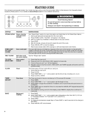
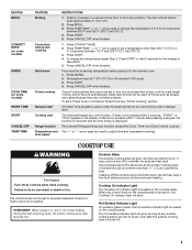
... Hazard Do not let food sit in 5° increments between 170°F and 525°F (75°C and 275°C). 3. Remove all of the range. OVEN LIGHT (on some models) Oven cavity light The oven light may have some or all racks and accessories from the oven cavity. 2. The oven... and helpful tips for the SteamClean feature. 1. Check that the oven is off . Only the CLOCK, OVEN LIGHT, and TIMER keypads will sound at www.whirlpool.com for 5 seconds. Press TIMER. 2. Press TIMER twice to this manual or the Frequently Asked Questions (FAQs) section of our website at end of -...
... Hazard Do not let food sit in 5° increments between 170°F and 525°F (75°C and 275°C). 3. Remove all of the range. OVEN LIGHT (on some models) Oven cavity light The oven light may have some or all racks and accessories from the oven cavity. 2. The oven... and helpful tips for the SteamClean feature. 1. Check that the oven is off . Only the CLOCK, OVEN LIGHT, and TIMER keypads will sound at www.whirlpool.com for 5 seconds. Press TIMER. 2. Press TIMER twice to this manual or the Frequently Asked Questions (FAQs) section of our website at end of -...
Owners Manual
Page 5
... Press BROIL. 3. To change the temperature in and turn on at a certain time of day, cook for an oven function with a delayed start Range function Temperature and time adjust INSTRUCTIONS 1. Press CANCEL/OFF when finished. or "PSH" appears in death or fire. Push in 5°F (5°C) ...;C and 275°C). 3. Press TEMP/TIME "+" or "-" arrow pads to setting. Food must be used to maintain the selected heat level. REMEMBER: When range is on. It may cycle on and off . 5 Cleaning off all controls when done cooking. Press CANCEL/OFF when finished. 1. The "+" or "-" ...
... Press BROIL. 3. To change the temperature in and turn on at a certain time of day, cook for an oven function with a delayed start Range function Temperature and time adjust INSTRUCTIONS 1. Press CANCEL/OFF when finished. or "PSH" appears in death or fire. Push in 5°F (5°C) ...;C and 275°C). 3. Press TEMP/TIME "+" or "-" arrow pads to setting. Food must be used to maintain the selected heat level. REMEMBER: When range is on. It may cycle on and off . 5 Cleaning off all controls when done cooking. Press CANCEL/OFF when finished. 1. The "+" or "-" ...


