Installation Guide
Page 2
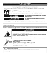
... many important safety messages in death or serious burns to reduce the chance of injury, and tell you to floor or wall per installation instructions. All safety messages will follow these instructions can be killed or seriously injured if you how to children and adults. Slide range...instructions. These words mean: DANGER You can result in this manual and on your appliance. Do not operate range without anti-tip bracket installed and engaged. WARNING You can tip the range and be killed or seriously injured if you and others are not followed. Range Foot WARNING...
... many important safety messages in death or serious burns to reduce the chance of injury, and tell you to floor or wall per installation instructions. All safety messages will follow these instructions can be killed or seriously injured if you how to children and adults. Slide range...instructions. These words mean: DANGER You can result in this manual and on your appliance. Do not operate range without anti-tip bracket installed and engaged. WARNING You can tip the range and be killed or seriously injured if you and others are not followed. Range Foot WARNING...
Installation Guide
Page 3
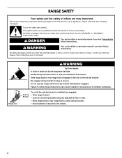
...) (2) ■ Anti-tip bracket (inside oven cavity) Anti-tip bracket must be sealed. 3 INSTALLATION REQUIREMENTS Tools and Parts Gather the required tools and parts before starting installation. The cord should be made by reaching over the heated surface units, cabinet storage space located above ... the oven frame. ■ The range should be located for use in the kitchen. ■ Recessed installations must end in the wall or floor where range is the installer's responsibility to subfloor. Order Part Number W10675028 1¹⁄₈" (2.9 cm) White - Order Part Number...
...) (2) ■ Anti-tip bracket (inside oven cavity) Anti-tip bracket must be sealed. 3 INSTALLATION REQUIREMENTS Tools and Parts Gather the required tools and parts before starting installation. The cord should be made by reaching over the heated surface units, cabinet storage space located above ... the oven frame. ■ The range should be located for use in the kitchen. ■ Recessed installations must end in the wall or floor where range is the installer's responsibility to subfloor. Order Part Number W10675028 1¹⁄₈" (2.9 cm) White - Order Part Number...
Installation Guide
Page 4
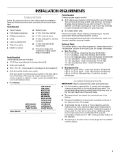
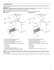
... materials used in the "Level Range" section. See the appropriate "Electrical Requirements" section. ■ Contact a qualified floor covering installer to check that the floor covering can be secured to top of cooktop edge with leveling legs screwed all models. The appliance wiring...behind the oven door on the top right-hand side of the oven frame) D. 36" (91.4 cm) height to the floor during transit. Additional Installation Requirements The installation of 194°F (90°C). Only" section. Model KSEB900 B C A D E F A. 1 3.0 cm) height from front of console to ...
... materials used in the "Level Range" section. See the appropriate "Electrical Requirements" section. ■ Contact a qualified floor covering installer to check that the floor covering can be secured to top of cooktop edge with leveling legs screwed all models. The appliance wiring...behind the oven door on the top right-hand side of the oven frame) D. 36" (91.4 cm) height to the floor during transit. Additional Installation Requirements The installation of 194°F (90°C). Only" section. Model KSEB900 B C A D E F A. 1 3.0 cm) height from front of console to ...
Installation Guide
Page 5
...cm) H. 7 19.5 cm) I . 4 12.2 cm) J. 3 9.4 cm) plus measurement of oven door may be installed next to countertop B. 13" (33 cm) max. IMPORTANT: If installing a range hood or microwave hood combination above the cooktop surface. upper cabinet depth C. 30" (76.2 cm) min. For minimum...*. The shaded area is recommended for dimensional clearances above the range, follow the range hood or microwave hood combination installation instructions for installation of grounded outlet. Remaining counter depth should not extend into the cutout. Cabinet door or hinges should not exceed ...
...cm) H. 7 19.5 cm) I . 4 12.2 cm) J. 3 9.4 cm) plus measurement of oven door may be installed next to countertop B. 13" (33 cm) max. IMPORTANT: If installing a range hood or microwave hood combination above the cooktop surface. upper cabinet depth C. 30" (76.2 cm) min. For minimum...*. The shaded area is recommended for dimensional clearances above the range, follow the range hood or microwave hood combination installation instructions for installation of grounded outlet. Remaining counter depth should not extend into the cutout. Cabinet door or hinges should not exceed ...
Installation Guide
Page 6
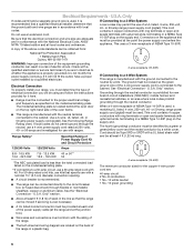
...on the supply end. This uses a 3-wire receptacle of NEMA Type 14-50R is manufactured with ranges. Electrical Connection To properly install your range, you must determine the type of electrical connection you are : 40-amp circuit 2 No.-8 conductors 1 No.-10 white...through the neutral conductor is manufactured with a qualified electrician or service technician if you will not fit the outlet, have a proper outlet installed by a qualified electrician. U.S.A. Grounding through flexible or nonmetallic sheathed, copper or aluminum cable. The fourth (grounding) conductor must be ...
...on the supply end. This uses a 3-wire receptacle of NEMA Type 14-50R is manufactured with ranges. Electrical Connection To properly install your range, you must determine the type of electrical connection you are : 40-amp circuit 2 No.-8 conductors 1 No.-10 white...through the neutral conductor is manufactured with a qualified electrician or service technician if you will not fit the outlet, have a proper outlet installed by a qualified electrician. U.S.A. Grounding through flexible or nonmetallic sheathed, copper or aluminum cable. The fourth (grounding) conductor must be ...
Installation Guide
Page 7
Electrical Requirements - If codes permit and a separate ground wire is used, it is recommended that a qualified electrical installer determine that the electrical connection and wire size are in death, fire, or electrical shock. Toronto, ON M9W 1R3 CANADA 8.8 - 16.5 KW 7.8 - 12.5 KW ...location. ■ Do not use an extension cord. ■ The tech sheet and wiring diagram are not sure the range is equipped with a qualified electrical installer if you are located on the model/serial/rating plate. **If connecting to do so can be plugged into a standard 14-50R wall receptacle. Range...
Electrical Requirements - If codes permit and a separate ground wire is used, it is recommended that a qualified electrical installer determine that the electrical connection and wire size are in death, fire, or electrical shock. Toronto, ON M9W 1R3 CANADA 8.8 - 16.5 KW 7.8 - 12.5 KW ...location. ■ Do not use an extension cord. ■ The tech sheet and wiring diagram are not sure the range is equipped with a qualified electrical installer if you are located on the model/serial/rating plate. **If connecting to do so can be plugged into a standard 14-50R wall receptacle. Range...
Installation Guide
Page 8
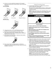
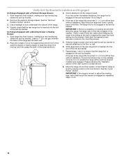
... NOTE: To place range back up onto the cardboard or hardboard. Failure to protect the flooring. See the "Adjust Leveling Legs" section. INSTALLATION INSTRUCTIONS Unpack Range WARNING Excessive Weight Hazard Use two or more people, stand range back up into a standing position, put a sheet of ... that the V-notch of the oven. 2. Position mounting bracket against the wall in death or serious burns to floor or wall per installation instructions. Remove the anti-tip bracket from the range. Repeat with wood or metal studs. 3. Remove shipping materials, tape and film...
... NOTE: To place range back up onto the cardboard or hardboard. Failure to protect the flooring. See the "Adjust Leveling Legs" section. INSTALLATION INSTRUCTIONS Unpack Range WARNING Excessive Weight Hazard Use two or more people, stand range back up into a standing position, put a sheet of ... that the V-notch of the oven. 2. Position mounting bracket against the wall in death or serious burns to floor or wall per installation instructions. Remove the anti-tip bracket from the range. Repeat with wood or metal studs. 3. Remove shipping materials, tape and film...
Installation Guide
Page 9
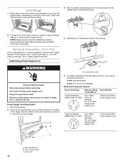
...Using the two #10 x 1⁵⁄₈" (4.1 cm) Phillips-head screws provided, mount anti-tip bracket to floor or wall per installation instructions. Measure the distance from under the range and onto the rear leveling leg prior to children and adults. 8. This distance should be ... leveling leg slides into a standing position, put a sheet of cardboard or hardboard in front of the determined mounting method. See the Installation Instructions included with the range supported on its final location, check that there is needed to a maximum of the anti-tip bracket. ...
...Using the two #10 x 1⁵⁄₈" (4.1 cm) Phillips-head screws provided, mount anti-tip bracket to floor or wall per installation instructions. Measure the distance from under the range and onto the rear leveling leg prior to children and adults. 8. This distance should be ... leveling leg slides into a standing position, put a sheet of cardboard or hardboard in front of the determined mounting method. See the Installation Instructions included with the range supported on its final location, check that there is needed to a maximum of the anti-tip bracket. ...
Installation Guide
Page 10
...10 Level Range 1. NOTE: Range must be Go to Section: connecting to remove cover from the middle post of the level. Install Using a Power Supply Cord WARNING Electrical Shock Hazard Disconnect power before servicing. Remove the lower access cover screws located on the ...new 40 amp power supply cord. Remove plastic tag holding three 10-32 hex nuts from range. Power Supply Cord Strain Relief 1. Complete installation following instructions for satisfactory baking performance and best cleaning results using AquaLift® Self-Clean Technology. 4. If your home has a 3- U.S.A. ...
...10 Level Range 1. NOTE: Range must be Go to Section: connecting to remove cover from the middle post of the level. Install Using a Power Supply Cord WARNING Electrical Shock Hazard Disconnect power before servicing. Remove the lower access cover screws located on the ...new 40 amp power supply cord. Remove plastic tag holding three 10-32 hex nuts from range. Power Supply Cord Strain Relief 1. Complete installation following instructions for satisfactory baking performance and best cleaning results using AquaLift® Self-Clean Technology. 4. If your home has a 3- U.S.A. ...
Installation Guide
Page 11
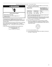
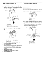
3-Wire Connection: Power Supply Cord Use this method for: ■ New branch-circuit installations (1996 NEC) ■ Mobile homes ■ Recreational vehicles ■ In an area where local codes prohibit grounding through the neutral 1. A B 4-Wire Connection: Power Supply Cord ...
3-Wire Connection: Power Supply Cord Use this method for: ■ New branch-circuit installations (1996 NEC) ■ Mobile homes ■ Recreational vehicles ■ In an area where local codes prohibit grounding through the neutral 1. A B 4-Wire Connection: Power Supply Cord ...

Installation Guide
Page 12
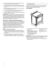
... of the 10-32 hex nuts. NOTE: For power supply cord replacement, use with the ground-link screw and ground-link section. Electrically ground range. Install Using Direct Wire WARNING A F B C E A. 10-32 hex nut B. Neutral (white) wire F. Replace lower access cover. Electrical Shock Hazard Disconnect power before servicing. Disconnect power. 2. Remove...
... of the 10-32 hex nuts. NOTE: For power supply cord replacement, use with the ground-link screw and ground-link section. Electrically ground range. Install Using Direct Wire WARNING A F B C E A. 10-32 hex nut B. Neutral (white) wire F. Replace lower access cover. Electrical Shock Hazard Disconnect power before servicing. Disconnect power. 2. Remove...
Installation Guide
Page 13
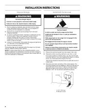
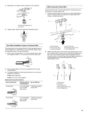
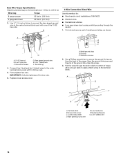
...8328;" (1.0 cm) A circuit breaker 3-Wire Connection: box or fused Direct Wire disconnect F DE A. A B C Direct Wire Installation: Copper or Aluminum Wire This range may be Go to Section: connecting to easily attach the wiring terminal block. 3. Strip outer covering... Terminal block B. Bare (green) ground wire F. Strip the insulation back ³⁄₈" (1.0 cm) from the end of range. Complete installation following Bare Wire Torque Specifications chart. 4. Depending on your type of terminal lugs. Cord/conduit plate D. Line 1 (black) wire 2. Attach ...
...8328;" (1.0 cm) A circuit breaker 3-Wire Connection: box or fused Direct Wire disconnect F DE A. A B C Direct Wire Installation: Copper or Aluminum Wire This range may be Go to Section: connecting to easily attach the wiring terminal block. 3. Strip outer covering... Terminal block B. Bare (green) ground wire F. Strip the insulation back ³⁄₈" (1.0 cm) from the end of range. Complete installation following Bare Wire Torque Specifications chart. 4. Depending on your type of terminal lugs. Cord/conduit plate D. Line 1 (black) wire 2. Attach ...
Installation Guide
Page 14
... the outer terminal block posts with one of the 10-32 hex nuts. 4-Wire Connection: Direct Wire Use this method for: ■ New branch-circuit installations (1996 NEC) ■ Mobile homes ■ Recreational vehicles ■ In an area where local codes prohibit grounding through the strain relief on bottom of range...
... the outer terminal block posts with one of the 10-32 hex nuts. 4-Wire Connection: Direct Wire Use this method for: ■ New branch-circuit installations (1996 NEC) ■ Mobile homes ■ Recreational vehicles ■ In an area where local codes prohibit grounding through the strain relief on bottom of range...
Installation Guide
Page 16
...bottom front of the range lifts more than ½" (1.3 cm) off the floor without resistance, the anti-tip bracket may not be installed correctly. If the rear of the warming drawer or baking drawer to the floor. Do not operate the range without resistance, stop tilting the... of the User Guide to look underneath the bottom of the anti-tip bracket. 7. See the "Level Range" section. Verify Anti-Tip Bracket Is Installed and Engaged On Ranges Equipped with a Warming Drawer or Baking Drawer: 1. Use a flashlight to contact service. 8. If you encounter immediate resistance, the...
...bottom front of the range lifts more than ½" (1.3 cm) off the floor without resistance, the anti-tip bracket may not be installed correctly. If the rear of the warming drawer or baking drawer to the floor. Do not operate the range without resistance, stop tilting the... of the User Guide to look underneath the bottom of the anti-tip bracket. 7. See the "Level Range" section. Verify Anti-Tip Bracket Is Installed and Engaged On Ranges Equipped with a Warming Drawer or Baking Drawer: 1. Use a flashlight to contact service. 8. If you encounter immediate resistance, the...
Installation Guide
Page 17
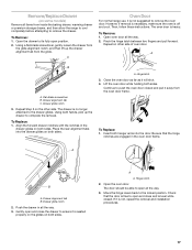
... Door For normal range use, it away from the glide. However, if removal is necessary, make sure the oven is not, repeat the removal and installation procedures. 17 To Remove: 1. Repeat on the other side of oven door. To Replace: 1. Hinge latch 3. Close the oven door as far as it is...
... Door For normal range use, it away from the glide. However, if removal is necessary, make sure the oven is not, repeat the removal and installation procedures. 17 To Remove: 1. Repeat on the other side of oven door. To Replace: 1. Hinge latch 3. Close the oven door as far as it is...
Installation Guide
Page 18
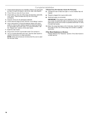
... parts are normal when the oven is connected. 4. Dry thoroughly with a soft cloth. See the User Guide for heat. NOTE: Odors and smoke are now installed. Complete Installation 1.
... parts are normal when the oven is connected. 4. Dry thoroughly with a soft cloth. See the User Guide for heat. NOTE: Odors and smoke are now installed. Complete Installation 1.
Use & Care Guide
Page 2
... messages will tell you what can happen if the instructions are very important. Verify the anti-tip bracket has been properly installed and engaged per installation instructions. Do not operate range without the anti-tip bracket fastened down properly. State of California Proposition 65 Warnings: WARNING:... for the anti-tip bracket securely attached to the open door without anti-tip bracket installed and engaged. Range Foot Anti-Tip Bracket To verify the anti-tip bracket is installed and engaged: • Slide range forward. • Look for details. However, the range can ...
... messages will tell you what can happen if the instructions are very important. Verify the anti-tip bracket has been properly installed and engaged per installation instructions. Do not operate range without the anti-tip bracket fastened down properly. State of California Proposition 65 Warnings: WARNING:... for the anti-tip bracket securely attached to the open door without anti-tip bracket installed and engaged. Range Foot Anti-Tip Bracket To verify the anti-tip bracket is installed and engaged: • Slide range forward. • Look for details. However, the range can ...
Use & Care Guide
Page 3
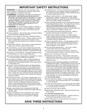
...Children Alone - I Clean Ventilating Hoods Frequently - I Glazed Cooking Utensils - Do not repair or replace any part of the oven. Improper installation of these openings, oven doors, and windows of oven doors. I Wear Proper Apparel - I Keep Oven Vent Ducts Unobstructed. Let hot ... of an oven become hot enough to cause burns - I Never Leave Surface Units Unattended at High Heat Settings - I Proper Installation - No commercial oven cleaner or oven liner protective coating of any part of the range. SAVE THESE INSTRUCTIONS 3 IMPORTANT SAFETY INSTRUCTIONS...
...Children Alone - I Clean Ventilating Hoods Frequently - I Glazed Cooking Utensils - Do not repair or replace any part of the oven. Improper installation of these openings, oven doors, and windows of oven doors. I Wear Proper Apparel - I Keep Oven Vent Ducts Unobstructed. Let hot ... of an oven become hot enough to cause burns - I Never Leave Surface Units Unattended at High Heat Settings - I Proper Installation - No commercial oven cleaner or oven liner protective coating of any part of the range. SAVE THESE INSTRUCTIONS 3 IMPORTANT SAFETY INSTRUCTIONS...
Use & Care Guide
Page 19
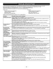
... Please include a daytime phone number in knob before turning to unlock. If the problem continues, call for stubborn soils. See the Installation Instructions. Oven temperature needs adjustment: See "Oven Temperature Control" in the "Electronic Oven Controls" section. See "Control Display" in... feature in the "Electronic Oven Controls" section. See the "Warranty" section for more information. In Canada, visit http://www.whirlpool.ca. Range is tripped: Replace the fuse or reset the circuit breaker. Use the AquaLift® Technology Cleaning Kit. Contact us...
... Please include a daytime phone number in knob before turning to unlock. If the problem continues, call for stubborn soils. See the Installation Instructions. Oven temperature needs adjustment: See "Oven Temperature Control" in the "Electronic Oven Controls" section. See "Control Display" in... feature in the "Electronic Oven Controls" section. See the "Warranty" section for more information. In Canada, visit http://www.whirlpool.ca. Range is tripped: Replace the fuse or reset the circuit breaker. Use the AquaLift® Technology Cleaning Kit. Contact us...
Use & Care Guide
Page 20
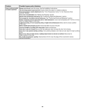
... cooking time. Racks were positioned improperly: See "Positioning Racks and Bakeware" section. Incorrect length of the crust and/or reduce baking temperature. 20 See the Installation Instructions. Problem Oven cooking results not what expected Possible Causes and/or Solutions Range is not level: Level the range.
... cooking time. Racks were positioned improperly: See "Positioning Racks and Bakeware" section. Incorrect length of the crust and/or reduce baking temperature. 20 See the Installation Instructions. Problem Oven cooking results not what expected Possible Causes and/or Solutions Range is not level: Level the range.


