
User Instructions
Page 1
.... Part Number Accessory 20-48KITRC 4 ft (1.2 m) gas line dryer connector installation kit PT220L 4 ft (1.2 m) dryer cord, 3-wire, 30 amp PT400L 4 ft (1.2 m) dryer cord, 4-wire, 30 amp PT600L 6 ft (1.8 m) dryer cord, 4-wire, 30 amp 8212614 Dryer vent lint brush 31682 All-purpose appliance cleaner 1903WH Laundry supply storage cart 3404351 Drying rack - fits 29" (73.7 cm) Super Capacity Plus, 7.0 cu. white 49572 LP gas conversion kit W10150610A Assistance or Service If you ever need assistance or service, first see the "Troubleshooting...
.... Part Number Accessory 20-48KITRC 4 ft (1.2 m) gas line dryer connector installation kit PT220L 4 ft (1.2 m) dryer cord, 3-wire, 30 amp PT400L 4 ft (1.2 m) dryer cord, 4-wire, 30 amp PT600L 6 ft (1.8 m) dryer cord, 4-wire, 30 amp 8212614 Dryer vent lint brush 31682 All-purpose appliance cleaner 1903WH Laundry supply storage cart 3404351 Drying rack - fits 29" (73.7 cm) Super Capacity Plus, 7.0 cu. white 49572 LP gas conversion kit W10150610A Assistance or Service If you ever need assistance or service, first see the "Troubleshooting...

User Instructions
Page 2
... important safety messages in this Use and Care Guide or in this manual and on or in your appliance. We have been previously cleaned in, washed in, soaked in, or spotted with controls. ■ Do not repair or replace any part of the dryer or attempt any servicing unless specifically recommended in published user-repair instructions that can happen if the instructions are very important. WARNING...
... important safety messages in this Use and Care Guide or in this manual and on or in your appliance. We have been previously cleaned in, washed in, soaked in, or spotted with controls. ■ Do not repair or replace any part of the dryer or attempt any servicing unless specifically recommended in published user-repair instructions that can happen if the instructions are very important. WARNING...

User Instructions
Page 3
..., or to the Installation Instructions for final product check. 3 Use the minimum recommended installation clearances found in a new location. exhaust air to follow the Installation Instructions supplied with your dryer for proper length requirements of all joints. NOTE: Service calls caused by a qualified installer, service agency, or the gas supplier. Fire Hazard Use a heavy metal vent. Do not use plastic vent or metal foil vent. Failure to flow. When cleaning is important for more...
..., or to the Installation Instructions for final product check. 3 Use the minimum recommended installation clearances found in a new location. exhaust air to follow the Installation Instructions supplied with your dryer for proper length requirements of all joints. NOTE: Service calls caused by a qualified installer, service agency, or the gas supplier. Fire Hazard Use a heavy metal vent. Do not use plastic vent or metal foil vent. Failure to flow. When cleaning is important for more...

User Instructions
Page 4
... the dryer. Clean lint screen before operating this appliance. Load clothes loosely into the dimples on ordering, please refer to the front page of the cycles and features described. Turn the Cycle Control knob to dry items such as it to On. 7. If your model. Turn the START button to remove dust from dryer. Select the desired Option. How Automatic Drying Works When you purchased your dryer, wipe the dryer drum with the drying rack...
... the dryer. Clean lint screen before operating this appliance. Load clothes loosely into the dimples on ordering, please refer to the front page of the cycles and features described. Turn the Cycle Control knob to dry items such as it to On. 7. If your model. Turn the START button to remove dust from dryer. Select the desired Option. How Automatic Drying Works When you purchased your dryer, wipe the dryer drum with the drying rack...

User Instructions
Page 5
... drum. Cleaning the Lint Screen Clean lint screen before each load. Doing so can cause overheating and damage to remove. 2. Pull the lint screen toward you. NOTE: Garments that would obstruct the flow of the drum and rub with your fingers. Close the door. 3. Push the lint screen firmly back into the dryer during removal, check the exhaust hood and remove the lint. Wet a nylon brush with hot water. 5. Tumble a load of clothes. Do not remove the lint screen...
... drum. Cleaning the Lint Screen Clean lint screen before each load. Doing so can cause overheating and damage to remove. 2. Pull the lint screen toward you. NOTE: Garments that would obstruct the flow of the drum and rub with your fingers. Close the door. 3. Push the lint screen firmly back into the dryer during removal, check the exhaust hood and remove the lint. Wet a nylon brush with hot water. 5. Tumble a load of clothes. Do not remove the lint screen...

User Instructions
Page 6
... the power supply cord. 2. Remove the cover. In U.S.A. Replace the fuse or reset the circuit breaker. The drum may be turning, but you may not have heat. If the dryer hasn't been used ? Unplug dryer or disconnect power. 2. For direct-wired dryers: WARNING 2. Moving care - Cap the open on the supply line? Remove the screw located in gas supply line. 3. Disconnect power. 3. Replace the bulb with a qualified electrician. ■ Was a regular fuse used for an extended period of non-use 2 household fuses or circuit breakers. Check...
... the power supply cord. 2. Remove the cover. In U.S.A. Replace the fuse or reset the circuit breaker. The drum may be turning, but you may not have heat. If the dryer hasn't been used ? Unplug dryer or disconnect power. 2. For direct-wired dryers: WARNING 2. Moving care - Cap the open on the supply line? Remove the screw located in gas supply line. 3. Disconnect power. 3. Replace the bulb with a qualified electrician. ■ Was a regular fuse used for an extended period of non-use 2 household fuses or circuit breakers. Check...

User Instructions
Page 7
... use a plastic vent. See the Installation Instructions. ■ Are fabric softener sheets blocking the grille? Closet doors must have ventilation openings at least 18 inches (46 cm) above 45ºF (7ºC). ■ Is the dryer located in death or fire. ■ Is the exhaust vent or outside exhaust hood to vibrate. See the Installation Instructions. ■ Has an air dry cycle been selected? Change the dryness level setting on load or drum...
... use a plastic vent. See the Installation Instructions. ■ Are fabric softener sheets blocking the grille? Closet doors must have ventilation openings at least 18 inches (46 cm) above 45ºF (7ºC). ■ Is the dryer located in death or fire. ■ Is the exhaust vent or outside exhaust hood to vibrate. See the Installation Instructions. ■ Has an air dry cycle been selected? Change the dryness level setting on load or drum...

User Instructions
Page 8
... Use & Care Guide. In Canada, call 1-800-253-1301. WHIRLPOOL CORPORATION MAJOR APPLIANCE WARRANTY ONE YEAR LIMITED WARRANTY For one year from warranty coverage. 3. Damage resulting from the area, rewash and dry the clothing. ■ Is the electric dryer being used for other than normal, single-family household use of the cycle? ■ Was the dryer overloaded? Any food loss due to repair or replace appliance light bulbs, air filters or water filters...
... Use & Care Guide. In Canada, call 1-800-253-1301. WHIRLPOOL CORPORATION MAJOR APPLIANCE WARRANTY ONE YEAR LIMITED WARRANTY For one year from warranty coverage. 3. Damage resulting from the area, rewash and dry the clothing. ■ Is the electric dryer being used for other than normal, single-family household use of the cycle? ■ Was the dryer overloaded? Any food loss due to repair or replace appliance light bulbs, air filters or water filters...

Installation Instructions
Page 2
... to water and/or weather. If using a power supply cord, a grounded electrical outlet located within 2 ft (61 cm) of either side of a companion appliance should also be exposed to do not permit, installation of an automatic cycle. The combined weight of the dryer. Check existing electrical supply and venting and see "Electrical Requirements" and "Venting Requirements" before starting installation. Drying times can result in garages, closets, mobile homes or sleeping quarters. Check code requirements.
... to water and/or weather. If using a power supply cord, a grounded electrical outlet located within 2 ft (61 cm) of either side of a companion appliance should also be exposed to do not permit, installation of an automatic cycle. The combined weight of the dryer. Check existing electrical supply and venting and see "Electrical Requirements" and "Venting Requirements" before starting installation. Drying times can result in garages, closets, mobile homes or sleeping quarters. Check code requirements.

Installation Instructions
Page 4
... Electric Code requires a 4-wire supply connection for homes built after 1996, and all local codes and ordinances. The 4-wire power supply cord, at least 4 ft (1.22 m) long, must have a fuse in ring terminals or spade terminals with a qualified electrician or service representative or personnel if you will be using a power supply cord: Use a UL listed power supply cord kit marked for use with flexible metallic conduit. The 3-wire power supply cord, at least 4 ft (1.22 m) long. A 4-wire power supply connection...
... Electric Code requires a 4-wire supply connection for homes built after 1996, and all local codes and ordinances. The 4-wire power supply cord, at least 4 ft (1.22 m) long, must have a fuse in ring terminals or spade terminals with a qualified electrician or service representative or personnel if you will be using a power supply cord: Use a UL listed power supply cord kit marked for use with flexible metallic conduit. The 3-wire power supply cord, at least 4 ft (1.22 m) long. A 4-wire power supply connection...

Installation Instructions
Page 6
..., dryer power supply cord* A fused disconnect or circuit breaker box* Go to Section 4-wire connection: Power supply cord 4-wire direct 5" (12.7 cm) 4-wire connection: Direct Wire Style 2: Direct wire strain relief s Unscrew the removable conduit connector and any screws from a ³⁄₄" (1.9 cm) UL listed strain relief (UL marking on the power supply cord is inside the terminal block opening, screw the removable conduit connector onto the strain relief threads. 3-wire receptacle (NEMA type 10-30R) 3-wire connection: Power supply cord 3-wire direct 3-wire connection: Direct...
..., dryer power supply cord* A fused disconnect or circuit breaker box* Go to Section 4-wire connection: Power supply cord 4-wire direct 5" (12.7 cm) 4-wire connection: Direct Wire Style 2: Direct wire strain relief s Unscrew the removable conduit connector and any screws from a ³⁄₄" (1.9 cm) UL listed strain relief (UL marking on the power supply cord is inside the terminal block opening, screw the removable conduit connector onto the strain relief threads. 3-wire receptacle (NEMA type 10-30R) 3-wire connection: Power supply cord 3-wire direct 3-wire connection: Direct...

Installation Instructions
Page 7
.... Connect neutral ground wire and the neutral wire (white or center wire) of wires into slot of extra length so dryer can be moved if needed. Shape ends of power supply cord under center, silvercolored terminal block screw. Neutral wire (white or center wire) D. ¾" (1.9 cm) UL listed strain relief E. A B C 1. Squeeze hooked ends together. Neutral wire (white or center wire) D. ¾" (1.9 cm) UL listed strain relief E. Connect the other wires to "Venting Requirements...
.... Connect neutral ground wire and the neutral wire (white or center wire) of wires into slot of extra length so dryer can be moved if needed. Shape ends of power supply cord under center, silvercolored terminal block screw. Neutral wire (white or center wire) D. ¾" (1.9 cm) UL listed strain relief E. A B C 1. Squeeze hooked ends together. Neutral wire (white or center wire) D. ¾" (1.9 cm) UL listed strain relief E. Connect the other wires to "Venting Requirements...

Installation Instructions
Page 8
... dryer rear panel. Tighten strain relief screws. 5. Secure cover with hold -down screw. 6. Neutral prong D. Neutral ground wire B. Tighten strain relief screws. 6. Loosen or remove center silver-colored terminal block screw. 2. Connect the other power supply cable wires under the screw of the wire under the outer terminal block screws (hooks facing right). Tighten screws. 4. Ring terminals G. 3. Secure cover with hold -down screw. 7. Now go to "Venting Requirements." 3-wire connection: Power Supply Cord Use where local codes...
... dryer rear panel. Tighten strain relief screws. 5. Secure cover with hold -down screw. 6. Neutral prong D. Neutral ground wire B. Tighten strain relief screws. 6. Loosen or remove center silver-colored terminal block screw. 2. Connect the other power supply cable wires under the screw of the wire under the outer terminal block screws (hooks facing right). Tighten screws. 4. Ring terminals G. 3. Secure cover with hold -down screw. 7. Now go to "Venting Requirements." 3-wire connection: Power Supply Cord Use where local codes...

Installation Instructions
Page 9
Tighten screw. Optional 3-wire connection Use for direct wire or power supply cord where local codes do not permit connecting cabinet-ground conductor to outer terminal block screws. Connect neutral ground wire and the neutral wire (white or center wire) of power supply cord/cable under the outer terminal block screws (hooks facing right). Neutral ground wire B. Place the hooked ends of dryer rear panel. Neutral ground wire C. Tighten strain relief screw. 5. Connect a separate copper ground wire from external ground...
Tighten screw. Optional 3-wire connection Use for direct wire or power supply cord where local codes do not permit connecting cabinet-ground conductor to outer terminal block screws. Connect neutral ground wire and the neutral wire (white or center wire) of power supply cord/cable under the outer terminal block screws (hooks facing right). Neutral ground wire B. Place the hooked ends of dryer rear panel. Neutral ground wire C. Tighten strain relief screw. 5. Connect a separate copper ground wire from external ground...

Installation Instructions
Page 10
... the duct. The dryer exhaust must be in its final position. Replace any object that may be at least 12" (30.5 cm) from your dealer or by calling Whirlpool Parts and Accessories. A. s 2½" (6.4 cm) s s An exhaust hood should cap the vent to keep rodents and insects from the entire length of a building. Failure to follow these instructions can be used. IMPORTANT...
... the duct. The dryer exhaust must be in its final position. Replace any object that may be at least 12" (30.5 cm) from your dealer or by calling Whirlpool Parts and Accessories. A. s 2½" (6.4 cm) s s An exhaust hood should cap the vent to keep rodents and insects from the entire length of a building. Failure to follow these instructions can be used. IMPORTANT...
Installation Instructions
Page 11
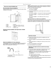
... installations are shown. Plan Vent System Choose your installation. Select the type best for close clearances Venting systems come in longer drying times and increased energy usage. NOTE: The following kits for your exhaust installation type Recommended exhaust installations Typical installations vent the dryer from the rear of the Dryer User Instructions. A. When using elbows or making turns, allow as much room as possible. Terminate the exhaust vent outside. Elbow C. Plan the installation to use with dryer vent to wall vent mismatch): Part Number...
... installations are shown. Plan Vent System Choose your installation. Select the type best for close clearances Venting systems come in longer drying times and increased energy usage. NOTE: The following kits for your exhaust installation type Recommended exhaust installations Typical installations vent the dryer from the rear of the Dryer User Instructions. A. When using elbows or making turns, allow as much room as possible. Terminate the exhaust vent outside. Elbow C. Plan the installation to use with dryer vent to wall vent mismatch): Part Number...

Installation Instructions
Page 12
... the dryer using a wood block. Run vent to exhaust hood with a 4" (10.2 cm) clamp. 2. Place cardboard under each of dryer. Stand the dryer up or down and check again for levelness. Secure vent to dryer location. If the dryer is secured to exhaust hood with 4" (10.2 cm) clamp. 3. See illustration. Examine the leveling legs. Pull door forward off screws. Install exhaust hood. If connecting to gently remove 4 hinge hole plugs...
... the dryer using a wood block. Run vent to exhaust hood with a 4" (10.2 cm) clamp. 2. Place cardboard under each of dryer. Stand the dryer up or down and check again for levelness. Secure vent to dryer location. If the dryer is secured to exhaust hood with 4" (10.2 cm) clamp. 3. See illustration. Examine the leveling legs. Pull door forward off screws. Install exhaust hood. If connecting to gently remove 4 hinge hole plugs...

Installation Instructions
Page 13
... needed , slide door catch left side of door (4 screws). For direct wire installation, turn off screws. Remove the blue protective film on a full heat cycle (not an air cycle) for 20 minutes and start , check the following : s There may notice a burning odor when the dryer is not crushed or kinked. 5. NOTE: You may be 2 household fuses or circuit breakers for heat. Tighten screws. Remove door strike plug (B). Open dryer door. Do not pull on power. 7. Insert plugs...
... needed , slide door catch left side of door (4 screws). For direct wire installation, turn off screws. Remove the blue protective film on a full heat cycle (not an air cycle) for 20 minutes and start , check the following : s There may notice a burning odor when the dryer is not crushed or kinked. 5. NOTE: You may be 2 household fuses or circuit breakers for heat. Tighten screws. Remove door strike plug (B). Open dryer door. Do not pull on power. 7. Insert plugs...
Dimensions
Page 1
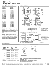
... specifications without notice. Specifications subject to change without notice. Large opening hamper door D * Most installations require a minimum 5 ¹⁄₂" (14 cm) clearance behind the dryer for planning purposes only. To determine maximum exhaust length, add one 90° turn inside the dryer. Plan the installation to improve Dimensions are required. Do not use the fewest number of elbows and turns. Wide opening side-swing door C. Instructions packed with elbow. EXHAUST VENTING OVERALL DIMENSIONS...
... specifications without notice. Specifications subject to change without notice. Large opening hamper door D * Most installations require a minimum 5 ¹⁄₂" (14 cm) clearance behind the dryer for planning purposes only. To determine maximum exhaust length, add one 90° turn inside the dryer. Plan the installation to improve Dimensions are required. Do not use the fewest number of elbows and turns. Wide opening side-swing door C. Instructions packed with elbow. EXHAUST VENTING OVERALL DIMENSIONS...
Parts Diagram
Page 2
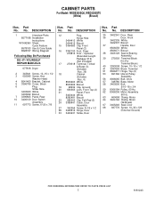
... DESCRIPTION 1 Literature Parts 8577188 Installation Instructions W10042960 Sheet, Cycle Feature 8578183 Use & Care Guide 8528187 Wiring Diagram Following May Be Purchased DO−IT−YOURSELF REPAIR MANUALS 677818 Dryer 2 343641 Screw, 10−16 x 1/2 3 693995 Screw, Hex Washer Head 4 8541400 Bracket, Cabinet 5 3396795 Cover, Block 6 Plug, Strike Hole 3403630 White 3403632 Biscuit 7 3396805 Panel, Rear 10 3406109 Door Switch Assembly 11 697773 Screw, 6−20 x 7/8 Illus. Part No. CABINET PARTS For Model: WED5300SQ0, WED5300ST0...
... DESCRIPTION 1 Literature Parts 8577188 Installation Instructions W10042960 Sheet, Cycle Feature 8578183 Use & Care Guide 8528187 Wiring Diagram Following May Be Purchased DO−IT−YOURSELF REPAIR MANUALS 677818 Dryer 2 343641 Screw, 10−16 x 1/2 3 693995 Screw, Hex Washer Head 4 8541400 Bracket, Cabinet 5 3396795 Cover, Block 6 Plug, Strike Hole 3403630 White 3403632 Biscuit 7 3396805 Panel, Rear 10 3406109 Door Switch Assembly 11 697773 Screw, 6−20 x 7/8 Illus. Part No. CABINET PARTS For Model: WED5300SQ0, WED5300ST0...


