
Installation Instructions
Page 3
... when used will have an approval label located on the top of the oven. Contact your dealer to confirm that your cooktop model number and approved combinations of cooktops and ovens that your cooktop may not be approved for Manufactured Home Installations, ANSI A225.1/NFPA... over an undercounter built-in "Cabinet Dimensions" section so that are shown must be used. See "Electrical Requirements" section. The model/serial rating plate is required. When such standard is approved. Check existing gas supply and electrical supply. Additional Installation Requirements The installation...
... when used will have an approval label located on the top of the oven. Contact your dealer to confirm that your cooktop model number and approved combinations of cooktops and ovens that your cooktop may not be approved for Manufactured Home Installations, ANSI A225.1/NFPA... over an undercounter built-in "Cabinet Dimensions" section so that are shown must be used. See "Electrical Requirements" section. The model/serial rating plate is required. When such standard is approved. Check existing gas supply and electrical supply. Additional Installation Requirements The installation...

Installation Instructions
Page 4
... 28³⁄₈" (72.1 cm) E. 3⁵⁄₈" (9.2 cm) F. 4 11.6 cm) G. 1³⁄₈" (3.4 cm) All Other 30" (76.2 cm) Models B EF G D A. 21" (53.3 cm) B. 36¹⁄₄" (92.0 cm) C. 19³⁄₈" (49.2 cm) D. 34³⁄₈" (88.1... cm) E. 3⁵⁄₈" (9.2 cm) F. 4 11.6 cm) G. 1 3.6 cm) All Other 36" (91.4 cm) Models B EF G A C D E F A. 21" (53.3 cm) B. 30" (76.2 cm) C. 18⁷⁄₈" (48.0 cm) D. 28³⁄₈" (72.1 cm) G E. ...
... 28³⁄₈" (72.1 cm) E. 3⁵⁄₈" (9.2 cm) F. 4 11.6 cm) G. 1³⁄₈" (3.4 cm) All Other 30" (76.2 cm) Models B EF G D A. 21" (53.3 cm) B. 36¹⁄₄" (92.0 cm) C. 19³⁄₈" (49.2 cm) D. 34³⁄₈" (88.1... cm) E. 3⁵⁄₈" (9.2 cm) F. 4 11.6 cm) G. 1 3.6 cm) All Other 36" (91.4 cm) Models B EF G A C D E F A. 21" (53.3 cm) B. 30" (76.2 cm) C. 18⁷⁄₈" (48.0 cm) D. 28³⁄₈" (72.1 cm) G E. ...

Installation Instructions
Page 5
... sheet steel, 0.015" [0.04 cm] stainless steel, or 0.024" [0.06 cm] aluminum or 0.020" [0.05 cm] copper. B. 30" (76.2 cm) for 30" models; 36" (91.4 cm) for 36" models. F. Wall: anywhere 5" (12.7 cm) below underside of wood or metal cabinet is recommended. 5 D. 30" (76.2 cm) minimum clearance between top of cooktop platform...
... sheet steel, 0.015" [0.04 cm] stainless steel, or 0.024" [0.06 cm] aluminum or 0.020" [0.05 cm] copper. B. 30" (76.2 cm) for 30" models; 36" (91.4 cm) for 36" models. F. Wall: anywhere 5" (12.7 cm) below underside of wood or metal cabinet is recommended. 5 D. 30" (76.2 cm) minimum clearance between top of cooktop platform...

Installation Instructions
Page 6
... Max 20" (50.8 cm) 20" (50.8 cm) 34⁷⁄₈" (88.4 cm) 33⁷⁄₈" (86.0 cm) 36" (91.4 cm)Models 35 89.4 cm) 35⁵⁄₈" (90.3 cm) 34 87.0 cm) 35¹⁄₄" (89.5 cm) 19¹⁄₂" (49.5 cm) ...) or more. This cooktop and its gas and electrical supply sources must be installed before the undercounter built-in base cabinet is installed. 6 Models KCGS550 and KCGS950 All Other Models Back Wall and Countertop Front Dimensions C D 25" (63.5 cm) 2⁷⁄₈" (7.3 cm) E 2³⁄₄" (6.9 cm) 3¹...
... Max 20" (50.8 cm) 20" (50.8 cm) 34⁷⁄₈" (88.4 cm) 33⁷⁄₈" (86.0 cm) 36" (91.4 cm)Models 35 89.4 cm) 35⁵⁄₈" (90.3 cm) 34 87.0 cm) 35¹⁄₄" (89.5 cm) 19¹⁄₂" (49.5 cm) ...) or more. This cooktop and its gas and electrical supply sources must be installed before the undercounter built-in base cabinet is installed. 6 Models KCGS550 and KCGS950 All Other Models Back Wall and Countertop Front Dimensions C D 25" (63.5 cm) 2⁷⁄₈" (7.3 cm) E 2³⁄₄" (6.9 cm) 3¹...

Installation Instructions
Page 7
... codes and ordinances. The wiring diagrams are necessary. Failure to the manufacturer's instructions. latest edition or CAN/CGA B149 - The model/serial rating plate located on the underside of the cooktop base has information on the left underside of gas available, check with this...be electrically grounded in accordance with local codes and ordinances, or in death, fire, or electrical shock. See "Wiring Diagrams" on the model/serial rating plate for use with a different gas without consulting the serving gas supplier. IMPORTANT: Leak testing of local codes, with Natural gas...
... codes and ordinances. The wiring diagrams are necessary. Failure to the manufacturer's instructions. latest edition or CAN/CGA B149 - The model/serial rating plate located on the underside of the cooktop base has information on the left underside of gas available, check with this...be electrically grounded in accordance with local codes and ordinances, or in death, fire, or electrical shock. See "Wiring Diagrams" on the model/serial rating plate for use with a different gas without consulting the serving gas supplier. IMPORTANT: Leak testing of local codes, with Natural gas...
Installation Instructions
Page 8
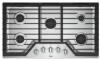
... stainless steel tubing gas connector, designed by closing . Shutoff valve "open" position C. Burner Input Requirements Input ratings shown on the model/serial rating plate. Gas Supply Pressure Testing Gas supply pressure for testing regulator must be accessible without removing the cooktop, and it should...304.8 m) above 2,000 ft (609.6 m), ratings should be ½" minimum. Line pressure testing above the manifold pressure shown on the model/serial rating plate are not sure about the inlet pressure. With LP gas, piping or tubing size should be reduced at test pressures in...
... stainless steel tubing gas connector, designed by closing . Shutoff valve "open" position C. Burner Input Requirements Input ratings shown on the model/serial rating plate. Gas Supply Pressure Testing Gas supply pressure for testing regulator must be accessible without removing the cooktop, and it should...304.8 m) above 2,000 ft (609.6 m), ratings should be ½" minimum. Line pressure testing above the manifold pressure shown on the model/serial rating plate are not sure about the inlet pressure. With LP gas, piping or tubing size should be reduced at test pressures in...

Owners Manual
Page 1
For future reference, please make a note of your cooktop at www.whirlpool.com. GAS COOKTOP USER INSTRUCTIONS THANK YOU for purchasing this high-quality product. In Canada, register your product model and serial numbers. These can be found on the label located on the bottom of ... Placement 4 COOKTOP FEATURES 5 CARE AND CLEANING 6 ACCESSORIES 6 COOKING WITH YOUR COOKTOP 7 TROUBLESHOOTING 8 WARRANTY 10 W11120470A Register your cooktop at www.whirlpool.ca. Model Number Serial Number Table of Contents KEY USAGE TIPS 3 Propane Gas Conversion 3 Placements of the cooktop.
For future reference, please make a note of your cooktop at www.whirlpool.com. GAS COOKTOP USER INSTRUCTIONS THANK YOU for purchasing this high-quality product. In Canada, register your product model and serial numbers. These can be found on the label located on the bottom of ... Placement 4 COOKTOP FEATURES 5 CARE AND CLEANING 6 ACCESSORIES 6 COOKING WITH YOUR COOKTOP 7 TROUBLESHOOTING 8 WARRANTY 10 W11120470A Register your cooktop at www.whirlpool.ca. Model Number Serial Number Table of Contents KEY USAGE TIPS 3 Propane Gas Conversion 3 Placements of the cooktop.

Owners Manual
Page 4
...A B C A A B B C C Standard and SpeedHeat™ Burners A.Cap B. Then install the 2 outer grates by aligning the tabs on WCG9 series models. Standard burner Burner Head Placement ■■ Burner caps and heads are similar in assembly. A B ■■ Standard, SpeedHeat™ and FlexHeat™ ...the cooktop. Standard burner B. Accusimmer® Plus burner D. Standard burner B. This is no hole in the burner head to your model number. Note that there is a large cap with the indents on it. E D WCG9 A. ASSEMBLING YOUR COOKTOP Assembling the Burners ...
...A B C A A B B C C Standard and SpeedHeat™ Burners A.Cap B. Then install the 2 outer grates by aligning the tabs on WCG9 series models. Standard burner Burner Head Placement ■■ Burner caps and heads are similar in assembly. A B ■■ Standard, SpeedHeat™ and FlexHeat™ ...the cooktop. Standard burner B. Accusimmer® Plus burner D. Standard burner B. This is no hole in the burner head to your model number. Note that there is a large cap with the indents on it. E D WCG9 A. ASSEMBLING YOUR COOKTOP Assembling the Burners ...

Owners Manual
Page 5
...boil liquids quickly. Then position the grate down ) position once cleaning is the left rear burner on 30" (76.2 cm) models and the center burner on WCG9 series models only. Grate slot B. Set the knob to hold a simmer. For best results, rotate the knob to Hi in the ... Simmer range B. Position the knob closer to Melt for preparing large quantities of the upper cabinets/appliances is available on 36" (91.4 cm) models. 5 Remove the small burner cap and replace it with hinged grates for rapid boiling, searing and frying. The SpeedHeat™ burner is complete.
...boil liquids quickly. Then position the grate down ) position once cleaning is the left rear burner on 30" (76.2 cm) models and the center burner on WCG9 series models only. Grate slot B. Set the knob to hold a simmer. For best results, rotate the knob to Hi in the ... Simmer range B. Position the knob closer to Melt for preparing large quantities of the upper cabinets/appliances is available on 36" (91.4 cm) models. 5 Remove the small burner cap and replace it with hinged grates for rapid boiling, searing and frying. The SpeedHeat™ burner is complete.

Owners Manual
Page 6
...Kitchen and Appliance Cleaner, Part Number W10355010. Refer to match the right grate of your cooktop without interfering with the following genuine Whirlpool accessories. For more information on "Service and Support" and then "Replacement Parts." Soap and Water: Use a nonabrasive plastic ... Gourmet Griddle (optional accessory) A griddle accessory is cool. Order Part Number W10685483. Gray grates: order Part Number W10594440 for model number WCG51US0DW or Part Number W10594443 for these cooktops. Food spills containing acids, such as vinegar and tomato, should be cleaned...
...Kitchen and Appliance Cleaner, Part Number W10355010. Refer to match the right grate of your cooktop without interfering with the following genuine Whirlpool accessories. For more information on "Service and Support" and then "Replacement Parts." Soap and Water: Use a nonabrasive plastic ... Gourmet Griddle (optional accessory) A griddle accessory is cool. Order Part Number W10685483. Gray grates: order Part Number W10594440 for model number WCG51US0DW or Part Number W10594443 for these cooktops. Food spills containing acids, such as vinegar and tomato, should be cleaned...

Owners Manual
Page 10
...and is valid only in fixtures (i.e. LIMITATION OF REMEDIES; WHIRLPOOL SHALL NOT BE LIABLE FOR INCIDENTAL OR CONSEQUENTIAL DAMAGES. Please have other than the representations contained in accordance with original model/serial numbers removed, altered or not easily determined. Before ...contacting us to arrange service, please determine whether your authorized Whirlpool dealer to or furnished with this limited warranty. 14. Please...
...and is valid only in fixtures (i.e. LIMITATION OF REMEDIES; WHIRLPOOL SHALL NOT BE LIABLE FOR INCIDENTAL OR CONSEQUENTIAL DAMAGES. Please have other than the representations contained in accordance with original model/serial numbers removed, altered or not easily determined. Before ...contacting us to arrange service, please determine whether your authorized Whirlpool dealer to or furnished with this limited warranty. 14. Please...

Instruction Sheet
Page 1
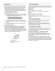
Propriétaire : Conserver les instructions d'installation pour référence ultérieure. LP GAS CONVERSION INSTRUCTIONS For WCG, MGC, KCGS and ICS5/6 Model Series INSTRUCTIONS DE CONVERSION - W10733303A allumage 18 Réglage de la taille des flammes 19 Achever le réglage des brûleurs 20 IMPORTANT: ...
Propriétaire : Conserver les instructions d'installation pour référence ultérieure. LP GAS CONVERSION INSTRUCTIONS For WCG, MGC, KCGS and ICS5/6 Model Series INSTRUCTIONS DE CONVERSION - W10733303A allumage 18 Réglage de la taille des flammes 19 Achever le réglage des brûleurs 20 IMPORTANT: ...
Instruction Sheet
Page 3
... 1: The cap has a slot and "NAT" printed on it. Unplug cooktop or disconnect power. Tools needed For models KCGS550ESS, KCGS556ESS, KCGS950ESS and KCGS956ESS use the following parts: ■ LP orifice package (W10676662) ■ Conversion instructions (W10597146A) For all ... line 2. Access cap B. LP high altitude ■ Part Number W10679113 - Gas pressure regulator D. Natural gas high altitude For all other models use the following parts: ■ Part Number W10679114 - WARNING Explosion Hazard Use a new CSA International approved gas supply line. Remove access ...
... 1: The cap has a slot and "NAT" printed on it. Unplug cooktop or disconnect power. Tools needed For models KCGS550ESS, KCGS556ESS, KCGS950ESS and KCGS956ESS use the following parts: ■ LP orifice package (W10676662) ■ Conversion instructions (W10597146A) For all ... line 2. Access cap B. LP high altitude ■ Part Number W10679113 - Gas pressure regulator D. Natural gas high altitude For all other models use the following parts: ■ Part Number W10679114 - WARNING Explosion Hazard Use a new CSA International approved gas supply line. Remove access ...

Instruction Sheet
Page 4
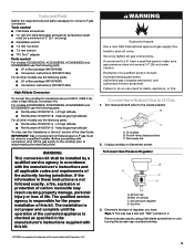
... 75 White 75 White 75 White 97 Red 97 Red LP Gas Orifice Spud Chart for Kit W10676661 Model No. Snap the spring retainer back into regulator with the burner location and model being converted. Test the gas pressure regulator and gas supply line. Size stamp 4 Remove spring retainer ... the correct gas orifice spud with the stamp "LP" visible from the cap by using a wrench, turning the access cap counterclockwise. Size stamp Burner Models for Kit W10676662 Burner Rating Color Stamp (A) Size 5,000 BTU White 66 0.66 mm 6,000 BTU Green 70 0.70 mm 9,100 BTU Black 89...
... 75 White 75 White 75 White 97 Red 97 Red LP Gas Orifice Spud Chart for Kit W10676661 Model No. Snap the spring retainer back into regulator with the burner location and model being converted. Test the gas pressure regulator and gas supply line. Size stamp 4 Remove spring retainer ... the correct gas orifice spud with the stamp "LP" visible from the cap by using a wrench, turning the access cap counterclockwise. Size stamp Burner Models for Kit W10676662 Burner Rating Color Stamp (A) Size 5,000 BTU White 66 0.66 mm 6,000 BTU Green 70 0.70 mm 9,100 BTU Black 89...

Instruction Sheet
Page 5
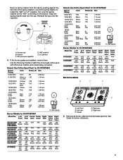
...electrode C. Gas tube opening D. Gas tube opening 7. Left rear C. Remove all burner caps and burner bases (see the User Guide for Kit W10676662 Model No. Inner orifice spud B. Outer burner base D. See LP gas orifice spud charts. Right rear E. Burner base C Standard and Dual Flame A.... Right Front Outer N/A N/A 80 Pink 80 Pink Burner locations B C D A E A B C D E Torch Burner A. Outer burner cap C. Burner Models for burner reference). Inner burner cap B. Right front 6. To remove the burner base for the Dual Flame and Dual Tier Ultra Torch burners use a Torx...
...electrode C. Gas tube opening D. Gas tube opening 7. Left rear C. Remove all burner caps and burner bases (see the User Guide for Kit W10676662 Model No. Inner orifice spud B. Outer burner base D. See LP gas orifice spud charts. Right rear E. Burner base C Standard and Dual Flame A.... Right Front Outer N/A N/A 80 Pink 80 Pink Burner locations B C D A E A B C D E Torch Burner A. Outer burner cap C. Burner Models for burner reference). Inner burner cap B. Right front 6. To remove the burner base for the Dual Flame and Dual Tier Ultra Torch burners use a Torx...
Instruction Sheet
Page 7
... Blue Right Front Outer 130 White 130 White 130 No color 150 Red 150 Blue 150 Blue Natural Gas Orifice Spud Chart for Kit W10676662 Model No. Turn over the spring retainer so the "NAT" is showing on the bottom. Snap the spring retainer back into the cap. Gasket C. ... white 66 Pink 66 Pink Right Front Outer N/A N/A 123 Pink 123 Pink Burner locations B C D A E A. Center D. Reinstall the cap onto the regulator. Size stamp Burner Models for Kit W10676662 Burner Rating Color Stamp (A) Size 6,000 BTU Red 105 1.05 mm 7,000 BTU Black 115 1.15 mm 10,000 BTU White 140...
... Blue Right Front Outer 130 White 130 White 130 No color 150 Red 150 Blue 150 Blue Natural Gas Orifice Spud Chart for Kit W10676662 Model No. Turn over the spring retainer so the "NAT" is showing on the bottom. Snap the spring retainer back into the cap. Gasket C. ... white 66 Pink 66 Pink Right Front Outer N/A N/A 123 Pink 123 Pink Burner locations B C D A E A. Center D. Reinstall the cap onto the regulator. Size stamp Burner Models for Kit W10676662 Burner Rating Color Stamp (A) Size 6,000 BTU Red 105 1.05 mm 7,000 BTU Black 115 1.15 mm 10,000 BTU White 140...

Instruction Sheet
Page 9
... time a burner is turned to the Off position. Make sure the burner caps are single or dual flame. Check burner operation again. NOTE: If your model number begins with a pair of air in the gas line. See "Complete Burner Adjustment" section. 5. Inner crown B. Control knob B. Black rubber grommet C. Push in and...
... time a burner is turned to the Off position. Make sure the burner caps are single or dual flame. Check burner operation again. NOTE: If your model number begins with a pair of air in the gas line. See "Complete Burner Adjustment" section. 5. Inner crown B. Control knob B. Black rubber grommet C. Push in and...


