
Use & Care Guide
Page 1
... 30" (76.2 CM) AND 36" (91.4 CM) RANGE HOOD Installation Instructions and Use & Care Guide For questions about features, operation/performance, parts, accessories or service, call: 1-800-253-1301 or visit our website at www.whirlpool.com In Canada, call 1-800-807-6777 or visit our website... Canada, pour assistance, installation ou service, composer le 1-800-807-6777 ou visiter notre site Web à www.whirlpool.ca Table of Contents/Table des matières 2 Models/Modèles: UXT5230AY/UXT5236AY IMPORTANT: READ AND SAVE THESE INSTRUCTIONS. IMPORTANT : LIRE ET CONSERVER CES INSTRUCTIONS.
... 30" (76.2 CM) AND 36" (91.4 CM) RANGE HOOD Installation Instructions and Use & Care Guide For questions about features, operation/performance, parts, accessories or service, call: 1-800-253-1301 or visit our website at www.whirlpool.com In Canada, call 1-800-807-6777 or visit our website... Canada, pour assistance, installation ou service, composer le 1-800-807-6777 ou visiter notre site Web à www.whirlpool.ca Table of Contents/Table des matières 2 Models/Modèles: UXT5230AY/UXT5236AY IMPORTANT: READ AND SAVE THESE INSTRUCTIONS. IMPORTANT : LIRE ET CONSERVER CES INSTRUCTIONS.

Use & Care Guide
Page 2
... Parts 4 Location Requirements 4 Venting Requirements 5 Electrical Requirements 6 INSTALLATION INSTRUCTIONS 7 Prepare Location 7 Install Range Hood 9 Make Electrical Connection 11 Complete Installation 11 RANGE HOOD USE 12 Range Hood Controls 12 RANGE HOOD CARE 12 Cleaning 12 WIRING DIAGRAM 14 ASSISTANCE OR SERVICE 15 In the U.S.A 15 In Canada 15 ...Nettoyage 28 SCHÉMA DE CÂBLAGE 30 ASSISTANCE OU SERVICE 31 Au Canada 31 Accessoires 31 GARANTIE 31 RANGE HOOD SAFETY Your safety and the safety of injury, and tell you and others are not followed. 2 We have ...
... Parts 4 Location Requirements 4 Venting Requirements 5 Electrical Requirements 6 INSTALLATION INSTRUCTIONS 7 Prepare Location 7 Install Range Hood 9 Make Electrical Connection 11 Complete Installation 11 RANGE HOOD USE 12 Range Hood Controls 12 RANGE HOOD CARE 12 Cleaning 12 WIRING DIAGRAM 14 ASSISTANCE OR SERVICE 15 In the U.S.A 15 In Canada 15 ...Nettoyage 28 SCHÉMA DE CÂBLAGE 30 ASSISTANCE OU SERVICE 31 Au Canada 31 Accessoires 31 GARANTIE 31 RANGE HOOD SAFETY Your safety and the safety of injury, and tell you and others are not followed. 2 We have ...

Use & Care Guide
Page 4
...Cabinet opening dimensions that all governing codes and ordinances. ■ It is located inside the range hood on the left wall. ■ Range hood location should be sealed. ■ These range hoods are shown must conform to comply with local codes. UL listed wire connectors ■ Vent ... (to attach filler strips). Given dimensions provide minimum clearance. See "Electrical Requirements" section. ■ All openings in ceiling and wall where range hood will be installed must be away from package. See the "Accessories" section to match vent system ■ 3 - Tools needed ■...
...Cabinet opening dimensions that all governing codes and ordinances. ■ It is located inside the range hood on the left wall. ■ Range hood location should be sealed. ■ These range hoods are shown must conform to comply with local codes. UL listed wire connectors ■ Vent ... (to attach filler strips). Given dimensions provide minimum clearance. See "Electrical Requirements" section. ■ All openings in ceiling and wall where range hood will be installed must be away from package. See the "Accessories" section to match vent system ■ 3 - Tools needed ■...

Use & Care Guide
Page 5
... back pressure and air turbulence that greatly reduce performance. If roof or wall cap has a damper, do not use damper supplied with a maximum length of range hood to cooking surface C. 30" (76.2 cm) min. B. Use 3¹⁄₄" x 10" (8.3 x 25.4 cm) rectangular with a maximum vent length of ...35 ft (10.7 m) or 7" (17.8 cm) or larger round vent with the range hood. ■ Use caulking to seal exterior wall or roof opening width for 30" (76.2 cm) models and 36" (91.4 cm) min. C C A. 7" (17.8...
... back pressure and air turbulence that greatly reduce performance. If roof or wall cap has a damper, do not use damper supplied with a maximum length of range hood to cooking surface C. 30" (76.2 cm) min. B. Use 3¹⁄₄" x 10" (8.3 x 25.4 cm) rectangular with a maximum vent length of ...35 ft (10.7 m) or 7" (17.8 cm) or larger round vent with the range hood. ■ Use caulking to seal exterior wall or roof opening width for 30" (76.2 cm) models and 36" (91.4 cm) min. C C A. 7" (17.8...

Use & Care Guide
Page 6
...: 1. If codes permit and a separate ground wire is used in conformance with the rating of the appliance as specified on the rear wall of the range hood. ■ Wire sizes must conform with National Electrical Code, ANSI/NFPA 70 (latest edition), or CSA Standards C22.1-94, Canadian Electrical Code, Part 1 and C22...
...: 1. If codes permit and a separate ground wire is used in conformance with the rating of the appliance as specified on the rear wall of the range hood. ■ Wire sizes must conform with National Electrical Code, ANSI/NFPA 70 (latest edition), or CSA Standards C22.1-94, Canadian Electrical Code, Part 1 and C22...

Use & Care Guide
Page 7
...on this line that is 2.2 cm) from the underside of the cabinet. Mark the point on the underside of cabinet. 2. Lift the range hood and set it upside down onto covered surface. 5. If cabinet has recessed bottom, add wood filler strips on your model, determine which venting...the centerline on the underside of cabinet. 3. Mark lines 5¼" (13.3 cm) to attach filler strips in the area the vent opening for assembling the range hood. Mark lines ¹⁄₂" (1.3 cm) and 4³⁄₄" (12.1 cm) from wall, not cabinet frame 3" (7.6 cm) Wood filler...
...on this line that is 2.2 cm) from the underside of the cabinet. Mark the point on the underside of cabinet. 2. Lift the range hood and set it upside down onto covered surface. 5. If cabinet has recessed bottom, add wood filler strips on your model, determine which venting...the centerline on the underside of cabinet. 3. Mark lines 5¼" (13.3 cm) to attach filler strips in the area the vent opening for assembling the range hood. Mark lines ¹⁄₂" (1.3 cm) and 4³⁄₄" (12.1 cm) from wall, not cabinet frame 3" (7.6 cm) Wood filler...

Use & Care Guide
Page 9
... pull the panel away from damper flap. b. Round vent knockout B. For roof installations, remove the top rectangular vent knockout. Install Range Hood 1. Remove the 2 bottom panels. Top rectangular vent knockout C. A B C D A A. Keyhole slot 5. Rear rectangular vent knockout... is not supplied. Do not remove any knockouts. 8. See the "Range Hood Care" section. 7. Remove the 3¼" x 10" (8.3 x 25.4 cm) rectangular vent damper taped on your range hood. 4. Lift the range hood up under cabinet and determine final location by centering beneath cabinet. Rectangular ...
... pull the panel away from damper flap. b. Round vent knockout B. For roof installations, remove the top rectangular vent knockout. Install Range Hood 1. Remove the 2 bottom panels. Top rectangular vent knockout C. A B C D A A. Keyhole slot 5. Rear rectangular vent knockout... is not supplied. Do not remove any knockouts. 8. See the "Range Hood Care" section. 7. Remove the 3¼" x 10" (8.3 x 25.4 cm) rectangular vent damper taped on your range hood. 4. Lift the range hood up under cabinet and determine final location by centering beneath cabinet. Rectangular ...

Use & Care Guide
Page 10
... UL listed or CSA approved ¹⁄₂" strain relief. Then push the hood toward the wall so that they interfere. ■ Non-vented (recirculating) installations - Hinge pin D. Position the range hood so that back draft dampers work properly. 10 C B A. Remove the vent ...the keyhole slots are over the mounting screws. B A C D E Power Supply Cable Installation 1. Terminal box cover B. Using 2 or more people, lift the hood into final position. Tighten the strain relief screws. 5. NOTE: The 7" (17.8 cm) round vent mounting plate and 3¹⁄₄" x 10" (8.3...
... UL listed or CSA approved ¹⁄₂" strain relief. Then push the hood toward the wall so that they interfere. ■ Non-vented (recirculating) installations - Hinge pin D. Position the range hood so that back draft dampers work properly. 10 C B A. Remove the vent ...the keyhole slots are over the mounting screws. B A C D E Power Supply Cable Installation 1. Terminal box cover B. Using 2 or more people, lift the hood into final position. Tighten the strain relief screws. 5. NOTE: The 7" (17.8 cm) round vent mounting plate and 3¹⁄₄" x 10" (8.3...

Use & Care Guide
Page 11
... ground the blower. Failure to green ground screw in place. 2. Check the operation of the panel clear the front mounting flange. See "Range Hood Use" section. Black wires C. Connect ground wire to do so can result in terminal box and securely tighten. 5. Install terminal box cover...1. UL listed or CSA approved ½" strain relief G. Green ground screw 2. Connect green (or bare) ground wire from your new range hood, read the "Range Hood Use" section. 11 Replace the 2 bottom panels. a. Push the front of the panel up into the rear channel and push the panel...
... ground the blower. Failure to green ground screw in place. 2. Check the operation of the panel clear the front mounting flange. See "Range Hood Use" section. Black wires C. Connect ground wire to do so can result in terminal box and securely tighten. 5. Install terminal box cover...1. UL listed or CSA approved ½" strain relief G. Green ground screw 2. Connect green (or bare) ground wire from your new range hood, read the "Range Hood Use" section. 11 Replace the 2 bottom panels. a. Push the front of the panel up into the rear channel and push the panel...

Use & Care Guide
Page 12
... ■ Rub in a dishwasher or hot detergent solution. On/Off light button B. Halogen lights B. Filter retainer Range Hood Controls A B CD RANGE HOOD CARE Cleaning IMPORTANT: Clean the hood and grease filters frequently according to remove fingerprints. Press the BLOWER OFF button a second time to 6 months with ...see the "Accessories" section. Blower speed maximum button Operating the light The On/Off light button controls both lights. RANGE HOOD USE The range hood is designed to clear all -purpose cleaner: Rinse with clean water and dry with soft, lint-free cloth. &#...
... ■ Rub in a dishwasher or hot detergent solution. On/Off light button B. Halogen lights B. Filter retainer Range Hood Controls A B CD RANGE HOOD CARE Cleaning IMPORTANT: Clean the hood and grease filters frequently according to remove fingerprints. Press the BLOWER OFF button a second time to 6 months with ...see the "Accessories" section. Blower speed maximum button Operating the light The On/Off light button controls both lights. RANGE HOOD USE The range hood is designed to clear all -purpose cleaner: Rinse with clean water and dry with soft, lint-free cloth. &#...

Use & Care Guide
Page 13
... push the front of the filter up on the lens and turn it counterclockwise. 3. Pull the filter retainer toward the front of the range hood. 2. Turn it clockwise to secure the filter. 4. Repeat steps 2-3 for the other lamps if needed. 5. Replace the screw into place to lock it ...filter retainer. Disconnect power. 2. Replace lamp, using tissue or wearing cotton gloves to cool. Push up into the channel at the rear of the range hood. To Replace the Filter: 1. Place the back edge of the new lamp, do not operate, make sure the lamps are inserted correctly before calling...
... push the front of the filter up on the lens and turn it counterclockwise. 3. Pull the filter retainer toward the front of the range hood. 2. Turn it clockwise to secure the filter. 4. Repeat steps 2-3 for the other lamps if needed. 5. Replace the screw into place to lock it ...filter retainer. Disconnect power. 2. Replace lamp, using tissue or wearing cotton gloves to cool. Push up into the channel at the rear of the range hood. To Replace the Filter: 1. Place the back edge of the new lamp, do not operate, make sure the lamps are inserted correctly before calling...

Installation Guide
Page 1
... 30" (76.2 CM) AND 36" (91.4 CM) RANGE HOOD Installation Instructions and Use & Care Guide For questions about features, operation/performance, parts, accessories or service, call: 1-800-253-1301 or visit our website at www.whirlpool.com In Canada, call 1-800-807-6777 or visit our ...Canada, pour assistance, installation ou service, composer le 1-800-807-6777 ou visiter notre site Web à www.whirlpool.ca Table of Contents/Table des matières 2 Models/Modèles: UXT5230AY/UXT5236AY IMPORTANT: READ AND SAVE THESE INSTRUCTIONS. IMPORTANT : LIRE ET CONSERVER CES INSTRUCTIONS.
... 30" (76.2 CM) AND 36" (91.4 CM) RANGE HOOD Installation Instructions and Use & Care Guide For questions about features, operation/performance, parts, accessories or service, call: 1-800-253-1301 or visit our website at www.whirlpool.com In Canada, call 1-800-807-6777 or visit our ...Canada, pour assistance, installation ou service, composer le 1-800-807-6777 ou visiter notre site Web à www.whirlpool.ca Table of Contents/Table des matières 2 Models/Modèles: UXT5230AY/UXT5236AY IMPORTANT: READ AND SAVE THESE INSTRUCTIONS. IMPORTANT : LIRE ET CONSERVER CES INSTRUCTIONS.
Installation Guide
Page 2
... 4 Location Requirements 4 Venting Requirements 5 Electrical Requirements 6 INSTALLATION INSTRUCTIONS 7 Prepare Location 7 Install Range Hood 9 Make Electrical Connection 11 Complete Installation 11 RANGE HOOD USE 12 Range Hood Controls 12 RANGE HOOD CARE 12 Cleaning 12 WIRING DIAGRAM 14 ASSISTANCE OR SERVICE 15 In the U.S.A 15 In Canada ... 28 SCHÉMA DE CÂBLAGE 30 ASSISTANCE OU SERVICE 31 Au Canada 31 Accessoires 31 GARANTIE 31 RANGE HOOD SAFETY Your safety and the safety of injury, and tell you don't immediately follow instructions. All safety messages will...
... 4 Location Requirements 4 Venting Requirements 5 Electrical Requirements 6 INSTALLATION INSTRUCTIONS 7 Prepare Location 7 Install Range Hood 9 Make Electrical Connection 11 Complete Installation 11 RANGE HOOD USE 12 Range Hood Controls 12 RANGE HOOD CARE 12 Cleaning 12 WIRING DIAGRAM 14 ASSISTANCE OR SERVICE 15 In the U.S.A 15 In Canada ... 28 SCHÉMA DE CÂBLAGE 30 ASSISTANCE OU SERVICE 31 Au Canada 31 Accessoires 31 GARANTIE 31 RANGE HOOD SAFETY Your safety and the safety of injury, and tell you don't immediately follow instructions. All safety messages will...

Installation Guide
Page 4
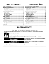
... all parts are shown must be used. See "Electrical Requirements" section. ■ All openings in ceiling and wall where range hood will be installed must conform to the Manufactured Home Construction Safety Standards, Title 24 CFR, Part 328 (formerly the Federal Standard...18⁵⁄₈" (47.3 cm) †®TORX is located inside the range hood on ordering, see the "Accessories" section. For information on the left wall. ■ Range hood location should be sealed. ■ These range hoods are capable of being installed as required For 7" (17.8 cm) round vented ...
... all parts are shown must be used. See "Electrical Requirements" section. ■ All openings in ceiling and wall where range hood will be installed must conform to the Manufactured Home Construction Safety Standards, Title 24 CFR, Part 328 (formerly the Federal Standard...18⁵⁄₈" (47.3 cm) †®TORX is located inside the range hood on ordering, see the "Accessories" section. For information on the left wall. ■ Range hood location should be sealed. ■ These range hoods are capable of being installed as required For 7" (17.8 cm) round vented ...
Installation Guide
Page 5
... for 30" (76.2 cm) models and 36" (91.4 cm) min. Roof cap with a maximum length of 50 ft (15.2 m) for vent system. bottom of range hood to provide efficient performance. cabinet opening around the cap. B. For the most efficient and quiet operation: ■ Use no more than three 90° elbows...) installations. ■ Do not terminate the vent system in your installation requirement. Roof Venting Wall Venting B A A B A. 18" (45.7 cm) min. Wall cap with the range hood. ■ Use caulking to seal exterior wall or roof opening width for 36" (91.4 cm) models.
... for 30" (76.2 cm) models and 36" (91.4 cm) min. Roof cap with a maximum length of 50 ft (15.2 m) for vent system. bottom of range hood to provide efficient performance. cabinet opening around the cap. B. For the most efficient and quiet operation: ■ Use no more than three 90° elbows...) installations. ■ Do not terminate the vent system in your installation requirement. Roof Venting Wall Venting B A A B A. 18" (45.7 cm) min. Wall cap with the range hood. ■ Use caulking to seal exterior wall or roof opening width for 36" (91.4 cm) models.

Installation Guide
Page 6
If codes permit and a separate ground wire is used in conformance with the rating of the appliance as specified on the rear wall of the range hood. ■ Wire sizes must conform with National Electrical Code, ANSI/NFPA 70 (latest edition), or CSA Standards C22.1-94, Canadian Electrical Code, Part 1 and C22.2 ...
If codes permit and a separate ground wire is used in conformance with the rating of the appliance as specified on the rear wall of the range hood. ■ Wire sizes must conform with National Electrical Code, ANSI/NFPA 70 (latest edition), or CSA Standards C22.1-94, Canadian Electrical Code, Part 1 and C22.2 ...

Installation Guide
Page 7
... Prepare Location NOTE: It is recommended that surface. 4. Disconnect power. Select a flat surface for wiring hole location instructions. 1. Lift the range hood and set it upside down onto covered surface. 5. Drill a 1¹⁄₄" (3.2 cm) diameter hole through top: 1. Mark a... line distance "A" from the back wall on each side. See Step 2 for assembling the range hood. Place covering over that the vent system be made. ⁷⁄₈" (2.2 cm) A Centerline A. 8³⁄₈" (21.3 cm) for...
... Prepare Location NOTE: It is recommended that surface. 4. Disconnect power. Select a flat surface for wiring hole location instructions. 1. Lift the range hood and set it upside down onto covered surface. 5. Drill a 1¹⁄₄" (3.2 cm) diameter hole through top: 1. Mark a... line distance "A" from the back wall on each side. See Step 2 for assembling the range hood. Place covering over that the vent system be made. ⁷⁄₈" (2.2 cm) A Centerline A. 8³⁄₈" (21.3 cm) for...

Installation Guide
Page 9
...: Your model will have a 3¼" x 10" (8.3 x 25.4 cm) rectangular vent damper on the inside your vent system installation. Set range hood aside on the range hood. Remove top rectangular and round vent knockouts. For roof installations, remove the top rectangular vent knockout. A B C D A A. Round vent knockout... 3.5 x 5 mm screws C. 7" (17.8 cm) round vent mounting plate (see the "Accessories" section. Push the panel toward the back of the range hood until the front tabs of the panel and pull the panel away from damper flap. Set panels aside. Mark on the underside of cabinet the...
...: Your model will have a 3¼" x 10" (8.3 x 25.4 cm) rectangular vent damper on the inside your vent system installation. Set range hood aside on the range hood. Remove top rectangular and round vent knockouts. For roof installations, remove the top rectangular vent knockout. A B C D A A. Round vent knockout... 3.5 x 5 mm screws C. 7" (17.8 cm) round vent mounting plate (see the "Accessories" section. Push the panel toward the back of the range hood until the front tabs of the panel and pull the panel away from damper flap. Set panels aside. Mark on the underside of cabinet the...

Installation Guide
Page 10
...two screws from the terminal box cover. Screw 3. Connect ventwork to make secure and airtight. 7. Vent knockouts E. Then push the hood toward the wall so that they interfere. ■ Non-vented (recirculating) installations - Remove the screw from the recirculation cover plate and... the ½" UL listed or CSA approved strain relief to the National Electric Code or CSA standards and local codes and ordinances. Position the range hood so that back draft dampers work properly. 10 Remove the vent connector damper flap if they do not interfere with damper B. 3.5 x 5 ...
...two screws from the terminal box cover. Screw 3. Connect ventwork to make secure and airtight. 7. Vent knockouts E. Then push the hood toward the wall so that they interfere. ■ Non-vented (recirculating) installations - Remove the screw from the recirculation cover plate and... the ½" UL listed or CSA approved strain relief to the National Electric Code or CSA standards and local codes and ordinances. Position the range hood so that back draft dampers work properly. 10 Remove the vent connector damper flap if they do not interfere with damper B. 3.5 x 5 ...

Installation Guide
Page 11
...White wires B. Connect ground wire to green ground screw in death, fire, or electrical shock. 4. Complete Installation 1. See the "Range Hood Care" section. 3. If range hood does not operate, check to do so can result in place. 2. Use UL listed wire connectors and connect black wires (B) together... connect white wires (A) together. Replace grease filter. Connect green (or bare) ground wire from your new range hood, read the "Range Hood Use" section. 11 WARNING Electrical Shock Hazard Disconnect power before operating. Failure to see whether a circuit breaker...
...White wires B. Connect ground wire to green ground screw in death, fire, or electrical shock. 4. Complete Installation 1. See the "Range Hood Care" section. 3. If range hood does not operate, check to do so can result in place. 2. Use UL listed wire connectors and connect black wires (B) together... connect white wires (A) together. Replace grease filter. Connect green (or bare) ground wire from your new range hood, read the "Range Hood Use" section. 11 WARNING Electrical Shock Hazard Disconnect power before operating. Failure to see whether a circuit breaker...


