Installation Guide
Page 2
... you what the potential hazard is the safety alert symbol. This is , tell you how to Hood Liner 12 Complete Installation and Check Operation 13 RANGE HOOD USE 14 Range Hood Controls 14 RANGE HOOD CARE 15 Cleaning 15 WIRING DIAGRAM 16 ASSISTANCE OR SERVICE 17 In the U.S.A 17 In Canada 17...DE LA HOTTE 32 Nettoyage 32 SCHÉMA DE CÂBLAGE 33 ASSISTANCE OU SERVICE 34 Au Canada 34 Accessoires 34 GARANTIE 35 RANGE HOOD SAFETY Your safety and the safety of injury, and tell you and others are not followed. 2 WARNING You can be killed or seriously injured...
... you what the potential hazard is the safety alert symbol. This is , tell you how to Hood Liner 12 Complete Installation and Check Operation 13 RANGE HOOD USE 14 Range Hood Controls 14 RANGE HOOD CARE 15 Cleaning 15 WIRING DIAGRAM 16 ASSISTANCE OR SERVICE 17 In the U.S.A 17 In Canada 17...DE LA HOTTE 32 Nettoyage 32 SCHÉMA DE CÂBLAGE 33 ASSISTANCE OU SERVICE 34 Au Canada 34 Accessoires 34 GARANTIE 35 RANGE HOOD SAFETY Your safety and the safety of injury, and tell you and others are not followed. 2 WARNING You can be killed or seriously injured...
Installation Guide
Page 3
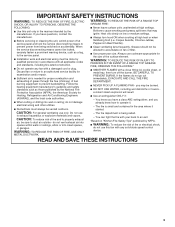
... IN THE EVENT OF A RANGE TOP GREASE FIRE, OBSERVE THE FOLLOWING:a ■ SMOTHER FLAMES with a close fitting lid, cookie sheet, or metal tray, then turn hood ON when cooking at high heat or when flambeing food (i.e. you already know you have questions, contact the manufacturer. ■ Before servicing or cleaning the...
... IN THE EVENT OF A RANGE TOP GREASE FIRE, OBSERVE THE FOLLOWING:a ■ SMOTHER FLAMES with a close fitting lid, cookie sheet, or metal tray, then turn hood ON when cooking at high heat or when flambeing food (i.e. you already know you have questions, contact the manufacturer. ■ Before servicing or cleaning the...
Installation Guide
Page 4
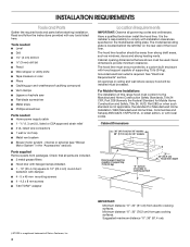
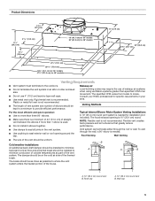
... (34 kg). INSTALLATION REQUIREMENTS Tools and Parts Gather the required tools and parts before starting installation. Check that are included. ■ 3 metal grease filters ■ Hood liner with halogen lamps installed. ■ 1 - 10" (25.4 cm) square to comply with damper. ■ 4 - 5 x 45 mm mounting screws ■..., or with any tools listed here. internal or external (see "Blower Motor System" in ceiling and wall where canopy hood will be installed must be sealed. Cabinet opening dimensions that all governing codes and ordinances. It is required. See "Electrical...
... (34 kg). INSTALLATION REQUIREMENTS Tools and Parts Gather the required tools and parts before starting installation. Check that are included. ■ 3 metal grease filters ■ Hood liner with halogen lamps installed. ■ 1 - 10" (25.4 cm) square to comply with damper. ■ 4 - 5 x 45 mm mounting screws ■..., or with any tools listed here. internal or external (see "Blower Motor System" in ceiling and wall where canopy hood will be installed must be sealed. Cabinet opening dimensions that all governing codes and ordinances. It is required. See "Electrical...
Installation Guide
Page 5
..." (25.4 cm) round vent system is 10" (25.4 cm) round. The break should be as close as part of the vent system. Wall cap 5 The hood exhaust opening around the cap. Flexible vent creates back pressure and air turbulence that greatly reduce performance. Roof cap A. 10" (25.4 cm) round vent B. NOTE...
..." (25.4 cm) round vent system is 10" (25.4 cm) round. The break should be as close as part of the vent system. Wall cap 5 The hood exhaust opening around the cap. Flexible vent creates back pressure and air turbulence that greatly reduce performance. Roof cap A. 10" (25.4 cm) round vent B. NOTE...
Installation Guide
Page 6
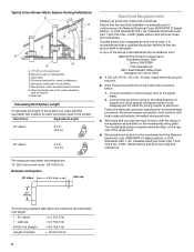
...-5575 ■ A 120 volt, 60 Hz., AC only, 15-amp, fused electrical circuit is located behind the filter on the rear wall of the range hood. ■ Wire sizes must conform with local codes and industry accepted wiring practices. ■ Wire sizes and connections must conform to trusses. Typical In-line...
...-5575 ■ A 120 volt, 60 Hz., AC only, 15-amp, fused electrical circuit is located behind the filter on the rear wall of the range hood. ■ Wire sizes must conform with local codes and industry accepted wiring practices. ■ Wire sizes and connections must conform to trusses. Typical In-line...
Installation Guide
Page 7
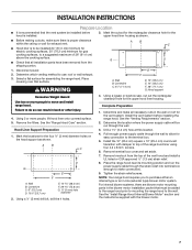
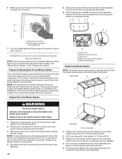
... run through the wall. 3. For internal blower systems, there are blower motor mounting parts in the wall or roof for assembling the range hood. Mark the cutout for the rectangular clearance hole for gas cooking surfaces, to use: roof or wall exhaust. 3. Using 2 or more ... in the blower motor installation packet that must be installed 24" (61.0 cm) minimum for electric cooking surfaces, 30" (76.2 cm) minimum for the upper hood liner housing as shown. Using a ¹⁄₈" (3 mm) drill bit, drill the 4 holes. 4. Complete Preparation 1. Determine and make connection). 9....
... run through the wall. 3. For internal blower systems, there are blower motor mounting parts in the wall or roof for assembling the range hood. Mark the cutout for the rectangular clearance hole for gas cooking surfaces, to use: roof or wall exhaust. 3. Using 2 or more ... in the blower motor installation packet that must be installed 24" (61.0 cm) minimum for electric cooking surfaces, 30" (76.2 cm) minimum for the upper hood liner housing as shown. Using a ¹⁄₈" (3 mm) drill bit, drill the 4 holes. 4. Complete Preparation 1. Determine and make connection). 9....
Installation Guide
Page 8
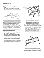
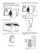
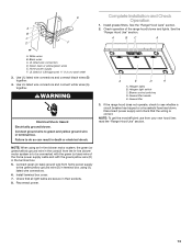
... top venting, the mounting bracket and spring clip that come with the screws. Prepare the Internal Blower System IMPORTANT: Perform steps 1-4 before mounting the hood liner. 1. Slide the mounting tab of the spring clip through the slot in the panel and secure with the blower system will mount to the ...of the square vent opening and the other four located at the proper location for the dual motor system. Using 2 or more people, lift the hood liner into the small square notches located at the proper location for the selected motor system. ■ Two 6 mm nuts are required for the...
... top venting, the mounting bracket and spring clip that come with the screws. Prepare the Internal Blower System IMPORTANT: Perform steps 1-4 before mounting the hood liner. 1. Slide the mounting tab of the spring clip through the slot in the panel and secure with the blower system will mount to the ...of the square vent opening and the other four located at the proper location for the dual motor system. Using 2 or more people, lift the hood liner into the small square notches located at the proper location for the selected motor system. ■ Two 6 mm nuts are required for the...
Installation Guide
Page 9
...3. Motor mounting plate hole B. Spring clip 5. quantity 5 for the dual motor system. Clip nut (6 mm) 9 Install the hood liner blower motor assembly inside the hood liner canopy with motor mounting clip nuts and install 6 x 16 mm screws and 6.4 mm lock washers (quantity 2 for single motor...mounting holes in the right end of the motor mounting plate up and snap it into the spring tab. A A A. Screw with lock washer B. Install Hood Liner Internal Blower Motor 1. Power supply wires and connector 4. A B A. AB A. A. Motor mounting plate B. NOTE: The spring tab should be ...
...3. Motor mounting plate hole B. Spring clip 5. quantity 5 for the dual motor system. Clip nut (6 mm) 9 Install the hood liner blower motor assembly inside the hood liner canopy with motor mounting clip nuts and install 6 x 16 mm screws and 6.4 mm lock washers (quantity 2 for single motor...mounting holes in the right end of the motor mounting plate up and snap it into the spring tab. A A A. Screw with lock washer B. Install Hood Liner Internal Blower Motor 1. Power supply wires and connector 4. A B A. AB A. A. Motor mounting plate B. NOTE: The spring tab should be ...
Installation Guide
Page 10
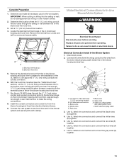
... mount, the blower motor assembly can result in -line blower motor housing and set it on the blower motor assembly. Pull the spring clip to Hood Liner" section. Plywood may be mounted using a 5 mm) drill bit. 3. Motor electrical plug Install In-line Blower System NOTE: The blower... motor system to move the in -line blower motor system. Using two or more people to the mounting location. 2. Remove the 10 screws from range hood 7. Position the in-line blower motor housing in the "Accessories" section. 6. Attach power cord connector from the housing and place it aside. A B ...
... mount, the blower motor assembly can result in -line blower motor housing and set it on the blower motor assembly. Pull the spring clip to Hood Liner" section. Plywood may be mounted using a 5 mm) drill bit. 3. Motor electrical plug Install In-line Blower System NOTE: The blower... motor system to move the in -line blower motor system. Using two or more people to the mounting location. 2. Remove the 10 screws from range hood 7. Position the in-line blower motor housing in the "Accessories" section. 6. Attach power cord connector from the housing and place it aside. A B ...
Installation Guide
Page 11
...Use UL listed wire connectors and connect the gray wires (G) together. 11 Locate the electrical terminal boxes in the in -line blower housing and hood liner electrical terminal boxes. 9. B A A. Remove the electrical knockout from the motor electrical plug cable inside the in-line blower housing terminal box... approved ¹⁄₂" (1.3 cm) wiring conduit and conduit connector. 6. Leave enough wire length in -line blower housing and hood liner. 7. Install the conduit connectors and conduit to the terminal boxes in the in each terminal box to do not damage electrical ...
...Use UL listed wire connectors and connect the gray wires (G) together. 11 Locate the electrical terminal boxes in the in -line blower housing and hood liner electrical terminal boxes. 9. B A A. Remove the electrical knockout from the motor electrical plug cable inside the in-line blower housing terminal box... approved ¹⁄₂" (1.3 cm) wiring conduit and conduit connector. 6. Leave enough wire length in -line blower housing and hood liner. 7. Install the conduit connectors and conduit to the terminal boxes in the in each terminal box to do not damage electrical ...
Installation Guide
Page 12
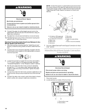
...185;⁄₂" (1.3 cm) wiring conduit B. Black wires D. Go to the "Make Electrical Power Supply Connection to Hood Liner WARNING 3. Locate terminal box inside the hood liner. 2. WARNING Electrical Shock Hazard Electrically ground blower. Connect ground wire to the green/yellow ground wire (H) in... green (or yellow/green) ground wire to green and yellow ground wire in the terminal box using UL listed wire connectors. With the hood liner mounted (see "Complete Preparation" in -line blower terminal box cover and screw. 10. Connect the 6-wire connector assembly supplied with ...
...185;⁄₂" (1.3 cm) wiring conduit B. Black wires D. Go to the "Make Electrical Power Supply Connection to Hood Liner WARNING 3. Locate terminal box inside the hood liner. 2. WARNING Electrical Shock Hazard Electrically ground blower. Connect ground wire to the green/yellow ground wire (H) in... green (or yellow/green) ground wire to green and yellow ground wire in the terminal box using UL listed wire connectors. With the hood liner mounted (see "Complete Preparation" in -line blower terminal box cover and screw. 10. Connect the 6-wire connector assembly supplied with ...
Installation Guide
Page 13
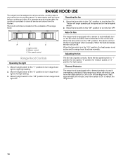
... green (or green/yellow) ground wire in the conduit from your new hood liner, read the "Range Hood Use" section. 13 Install terminal box cover. 7. Blower control switches D. Grease filter 3. If the range hood does not operate, check to green and yellow ground wire in the terminal... box. 5. See the "Range Hood Care" section. WARNING Electrical Shock Hazard Electrically ground blower. Failure to be connected with ...
... green (or green/yellow) ground wire in the conduit from your new hood liner, read the "Range Hood Use" section. 13 Install terminal box cover. 7. Blower control switches D. Grease filter 3. If the range hood does not operate, check to green and yellow ground wire in the terminal... box. 5. See the "Range Hood Care" section. WARNING Electrical Shock Hazard Electrically ground blower. Failure to be connected with ...
Installation Guide
Page 14
... to operate several minutes after the cooking is complete to remove smoke, cooking vapors and odors from the kitchen. Adjusting the fan Range Hood Controls Operating the light 1. The hood controls are located on the fan speed switch. 2. The fan has 3 speed controls. Move the fan switch to the "Off" ...position to turn the fan to restart the range hood. 14 Blower control C. When the fan switch is in use, move slider to On to high speed when necessary. Fan speed control The range...
... to operate several minutes after the cooking is complete to remove smoke, cooking vapors and odors from the kitchen. Adjusting the fan Range Hood Controls Operating the light 1. The hood controls are located on the fan speed switch. 2. The fan has 3 speed controls. Move the fan switch to the "Off" ...position to turn the fan to restart the range hood. 14 Blower control C. When the fan switch is in use, move slider to On to high speed when necessary. Fan speed control The range...
Installation Guide
Page 15
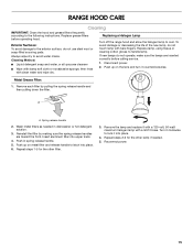
...steel wool or soap-filled scouring pads. Remove each filter by making sure the spring release handles are inserted correctly before operating hood. Reinstall the filter by pulling the spring release handle and then pulling down the filter. Repeat steps 2-3 for the other ...filter into place. 4. Wash metal filters as needed . 5. Always wipe dry to the following instructions. Replacing a Halogen Lamp Turn off the range hood and allow the halogen lamp to handle lamp. Replace lamp, using tissue or wearing cotton gloves to cool. Disconnect power. 2. Metal Grease Filter:...
...steel wool or soap-filled scouring pads. Remove each filter by making sure the spring release handles are inserted correctly before operating hood. Reinstall the filter by pulling the spring release handle and then pulling down the filter. Repeat steps 2-3 for the other ...filter into place. 4. Wash metal filters as needed . 5. Always wipe dry to the following instructions. Replacing a Halogen Lamp Turn off the range hood and allow the halogen lamp to handle lamp. Replace lamp, using tissue or wearing cotton gloves to cool. Disconnect power. 2. Metal Grease Filter:...
Installation Guide
Page 17
... etc.). ■ Referrals to fulfill the product warranty and provide afterwarranty service, anywhere in Canada. Whirlpool Canada LP designated service technicians are made with the 48" hood liner. 600 CFM Internal Blower Motor System - Order Model Number UXB0600DYS 1200 CFM Internal Blower Motor ...Order Model Number UXI1200DYS 17 Mississauga, Ontario L5N 0B7 Please include a daytime phone number in your area, you can write to Whirlpool Corporation with a maximum of your correspondence. If you need replacement parts If you need further assistance, you use in your ...
... etc.). ■ Referrals to fulfill the product warranty and provide afterwarranty service, anywhere in Canada. Whirlpool Canada LP designated service technicians are made with the 48" hood liner. 600 CFM Internal Blower Motor System - Order Model Number UXB0600DYS 1200 CFM Internal Blower Motor ...Order Model Number UXI1200DYS 17 Mississauga, Ontario L5N 0B7 Please include a daytime phone number in your area, you can write to Whirlpool Corporation with a maximum of your correspondence. If you need replacement parts If you need further assistance, you use in your ...
Dimension Guide
Page 1
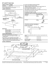
...straight = 8.0 ft (2.4 m) Length of the vent should be uniform. OVERALL DIMENSIONS The maximum equivalent vent lengths are for 48" models Because Whirlpool Corporation policy includes a continuous commitment to the outdoors. Minimum distance "X": 30" (76.2 cm) from electric cooking surfaces. q Do not use... example falls within the maximum recommended vent length. 1 - 90° elbow = 5.0 ft (1.5 m) 1 - 36" and 48" Hood Liner PRODUCT MODEL NUMBERS UXL6036Y UXL6048Y Electrical Requirements: A 120-volt, 60-Hz, AC-only, 15-amp, fused electrical circuit is recommended. ...
...straight = 8.0 ft (2.4 m) Length of the vent should be uniform. OVERALL DIMENSIONS The maximum equivalent vent lengths are for 48" models Because Whirlpool Corporation policy includes a continuous commitment to the outdoors. Minimum distance "X": 30" (76.2 cm) from electric cooking surfaces. q Do not use... example falls within the maximum recommended vent length. 1 - 90° elbow = 5.0 ft (1.5 m) 1 - 36" and 48" Hood Liner PRODUCT MODEL NUMBERS UXL6036Y UXL6048Y Electrical Requirements: A 120-volt, 60-Hz, AC-only, 15-amp, fused electrical circuit is recommended. ...


