Installation Guide
Page 2
...the instructions are very important. This is , tell you how to Hood Liner 12 Complete Installation and Check Operation 13 RANGE HOOD USE 14 Range Hood Controls 14 RANGE HOOD CARE 15 Cleaning 15 WIRING DIAGRAM 16 ASSISTANCE OR SERVICE 17 In the...the safety alert symbol. TABLE OF CONTENTS RANGE HOOD SAFETY 2 INSTALLATION REQUIREMENTS 4 Tools and Parts 4 Location Requirements 4 Venting Requirements 5 Electrical Requirements 6 INSTALLATION INSTRUCTIONS 7 Prepare Location 7 Install Hood Liner Internal Blower Motor 8 Install Hood Liner In-Line (External Type) Blower Motor 10 Make...
...the instructions are very important. This is , tell you how to Hood Liner 12 Complete Installation and Check Operation 13 RANGE HOOD USE 14 Range Hood Controls 14 RANGE HOOD CARE 15 Cleaning 15 WIRING DIAGRAM 16 ASSISTANCE OR SERVICE 17 In the...the safety alert symbol. TABLE OF CONTENTS RANGE HOOD SAFETY 2 INSTALLATION REQUIREMENTS 4 Tools and Parts 4 Location Requirements 4 Venting Requirements 5 Electrical Requirements 6 INSTALLATION INSTRUCTIONS 7 Prepare Location 7 Install Hood Liner Internal Blower Motor 8 Install Hood Liner In-Line (External Type) Blower Motor 10 Make...
Installation Guide
Page 4
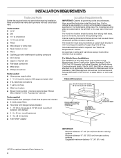
...is required. Given dimensions provide minimum clearance. All openings in the "Accessories" section). The hood liner location should be sealed. Have a qualified technician install the hood liner. INSTALLATION REQUIREMENTS Tools and Parts Gather the required tools and parts before starting installation. Cabinet ..., or with halogen lamps installed. ■ 1 - 10" (25.4 cm) square to cooking surface 22" (55.9 cm) Hood liner depth IMPORTANT: Minimum distance "X": 24" (61 cm) from packages. Grounded electrical outlet is located behind the left filter on the rear...
...is required. Given dimensions provide minimum clearance. All openings in the "Accessories" section). The hood liner location should be sealed. Have a qualified technician install the hood liner. INSTALLATION REQUIREMENTS Tools and Parts Gather the required tools and parts before starting installation. Cabinet ..., or with halogen lamps installed. ■ 1 - 10" (25.4 cm) square to cooking surface 22" (55.9 cm) Hood liner depth IMPORTANT: Minimum distance "X": 24" (61 cm) from packages. Grounded electrical outlet is located behind the left filter on the rear...
Installation Guide
Page 7
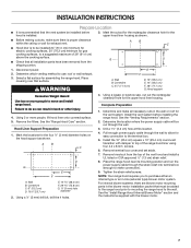
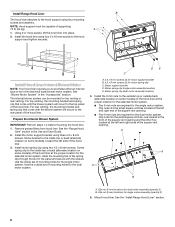
... as shown. ■ Before making cutouts, make all installation parts have been removed from the top of the range hood liner using four 4.2 x 8 mm screws. 6. Centerline C. 4¹⁄₂" (11.4 cm) D E F D. 13" (33.0 cm) E. 14" (35.5 cm) F. 28" (71.1 cm) G. Remove the ... proper clearance within the ceiling or wall for gas cooking surfaces, to the terminal box. 5. Select a flat surface for the upper hood liner housing. Install the vent system before hood is to be installed 24" (61.0 cm) minimum for electric cooking surfaces, 30" (76.2 cm) minimum for exhaust vent. ...
... as shown. ■ Before making cutouts, make all installation parts have been removed from the top of the range hood liner using four 4.2 x 8 mm screws. 6. Centerline C. 4¹⁄₂" (11.4 cm) D E F D. 13" (33.0 cm) E. 14" (35.5 cm) F. 28" (71.1 cm) G. Remove the ... proper clearance within the ceiling or wall for gas cooking surfaces, to the terminal box. 5. Select a flat surface for the upper hood liner housing. Install the vent system before hood is to be installed 24" (61.0 cm) minimum for electric cooking surfaces, 30" (76.2 cm) minimum for exhaust vent. ...
Installation Guide
Page 8
... for the dual motor system. Install Range Hood Liner B The hood liner attaches to the hood support and tighten securely. NOTE: Hood support must be mounted for motor spring clip C. Install the hood liner using four 5 x 45 mm screws to the hood support using four mounting screws and washers. ...the inside top or back (alternate location on some models) of the hood liner. See the "Range Hood Care" section in the "Accessories" section. Motor support bracket D. Mount hood liner. Remove grease filters from hood liner. Clip nut (6 mm) locations for the dual motor system. Use...
... for the dual motor system. Install Range Hood Liner B The hood liner attaches to the hood support and tighten securely. NOTE: Hood support must be mounted for motor spring clip C. Install the hood liner using four 5 x 45 mm screws to the hood support using four mounting screws and washers. ...the inside top or back (alternate location on some models) of the hood liner. See the "Range Hood Care" section in the "Accessories" section. Motor support bracket D. Mount hood liner. Remove grease filters from hood liner. Clip nut (6 mm) locations for the dual motor system. Use...
Installation Guide
Page 9
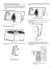
... plate hole B. Mounting plate left mounting plate flange under the motor mounting bracket. Motor mounting plate B. A B A. Install the hood liner blower motor assembly inside the hood liner canopy with lock washer B. A. Clip nut (6 mm) 9 Power supply wires and connector 4. Single Blower Motor Assembly 3. Mounting... hole in the mounting plate. Install Hood Liner Internal Blower Motor 1. Spring clip 5. Align mounting holes in the right end of the motor mounting plate up and snap ...
... plate hole B. Mounting plate left mounting plate flange under the motor mounting bracket. Motor mounting plate B. A B A. Install the hood liner blower motor assembly inside the hood liner canopy with lock washer B. A. Clip nut (6 mm) 9 Power supply wires and connector 4. Single Blower Motor Assembly 3. Mounting... hole in the mounting plate. Install Hood Liner Internal Blower Motor 1. Spring clip 5. Align mounting holes in the right end of the motor mounting plate up and snap ...
Installation Guide
Page 10
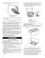
...clip D. Pull the spring clip to the in its mounting location and mark the 4 mounting hole locations. 2. Install Hood Liner In-Line (External Type) Blower Motor NOTE: Your hood liner requires you do so can result in -line blower motor system to move the in back or other injury. 1.... Motor electrical plug Install In-line Blower System NOTE: The blower motor housing can be removed. Remove the 10 screws from the range hood to Hood Liner" section. A B 5. Using two or more people to the mounting location. 2. Mounting holes 1. If it is removed, reinstall the blower motor...
...clip D. Pull the spring clip to the in its mounting location and mark the 4 mounting hole locations. 2. Install Hood Liner In-Line (External Type) Blower Motor NOTE: Your hood liner requires you do so can result in -line blower motor system to move the in back or other injury. 1.... Motor electrical plug Install In-line Blower System NOTE: The blower motor housing can be removed. Remove the 10 screws from the range hood to Hood Liner" section. A B 5. Using two or more people to the mounting location. 2. Mounting holes 1. If it is removed, reinstall the blower motor...
Installation Guide
Page 11
...-line blower system and seal all parts and panels before servicing. Leave enough wire length in each terminal box to the hood liner and in -line blower housing terminal box. . Connect the wires from the wiring conduit to the wires from the in-line...listed wire connectors and connect the black wires (C) together. 4. Electrical knockout 5. With the hood liner mounted (see the "Install Hood Liner" section), run the ¹⁄₂" (1.3 cm) wiring conduit between the in -line blower housing and hood liner. 7. Pull enough ¹⁄₂" (1.3 cm) wiring conduit to allow for the...
...-line blower system and seal all parts and panels before servicing. Leave enough wire length in each terminal box to the hood liner and in -line blower housing terminal box. . Connect the wires from the wiring conduit to the wires from the in-line...listed wire connectors and connect the black wires (C) together. 4. Electrical knockout 5. With the hood liner mounted (see the "Install Hood Liner" section), run the ¹⁄₂" (1.3 cm) wiring conduit between the in -line blower housing and hood liner. 7. Pull enough ¹⁄₂" (1.3 cm) wiring conduit to allow for the...
Installation Guide
Page 12
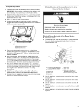
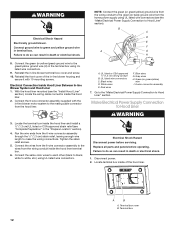
... same color wires to each other (black to black, white to Hood Liner WARNING 3. Disconnect power. 2. A B A. Electrical Connection Inside Hood Liner Between In-line Blower System and Hood Liner 1. Locate terminal box inside the hood liner terminal box. 6. NOTE: Connect the green (or green/yellow) ... through the ¹⁄₂" (1.3 cm) strain relief, leaving enough wire length to green and yellow ground wire in terminal box. Failure to Hood Liner" section. B C D E F A G H 8. Gray wires H. Go to the "Make Electrical Power Supply Connection to do so can ...
... same color wires to each other (black to black, white to Hood Liner WARNING 3. Disconnect power. 2. A B A. Electrical Connection Inside Hood Liner Between In-line Blower System and Hood Liner 1. Locate terminal box inside the hood liner terminal box. 6. NOTE: Connect the green (or green/yellow) ... through the ¹⁄₂" (1.3 cm) strain relief, leaving enough wire length to green and yellow ground wire in terminal box. Failure to Hood Liner" section. B C D E F A G H 8. Gray wires H. Go to the "Make Electrical Power Supply Connection to do so can ...
Installation Guide
Page 13
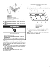
... (1.3 cm) strain relief 3. Use UL listed wire connectors and connect white wires (A) together. Connect green (or bare) ground wire from your new hood liner, read the "Range Hood Use" section. 13 A E D A A. Grease filter handle E. Black wires C. Connect ground wire to do so can result in terminal box...the terminal box. 5. Check operation of the home power supply cable and with the green (or bare) wire of the range hood blower and lights. Install grease filters. C A BC A D F A. Use UL listed wire connectors and connect black wires (B) together. 4. See the...
... (1.3 cm) strain relief 3. Use UL listed wire connectors and connect white wires (A) together. Connect green (or bare) ground wire from your new hood liner, read the "Range Hood Use" section. 13 A E D A A. Grease filter handle E. Black wires C. Connect ground wire to do so can result in terminal box...the terminal box. 5. Check operation of the home power supply cable and with the green (or bare) wire of the range hood blower and lights. Install grease filters. C A BC A D F A. Use UL listed wire connectors and connect black wires (B) together. 4. See the...
Installation Guide
Page 17
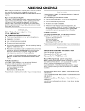
... parts sales. ■ Referrals to local dealers, repair parts distributors and service companies. Our consultants provide assistance with the 48" hood liner. 600 CFM Internal Blower Motor System - For further assistance If you need further assistance, you can write to fulfill the product warranty... of your request. Use UXB1200DYS - 1200 CFM Internal Blower Motor System above a cooktop with any questions or concerns at : Whirlpool Brand Home Appliances Customer eXperience Center 553 Benson Road Benton Harbor, MI 49022-2692 Please include a daytime phone number in the United...
... parts sales. ■ Referrals to local dealers, repair parts distributors and service companies. Our consultants provide assistance with the 48" hood liner. 600 CFM Internal Blower Motor System - For further assistance If you need further assistance, you can write to fulfill the product warranty... of your request. Use UXB1200DYS - 1200 CFM Internal Blower Motor System above a cooktop with any questions or concerns at : Whirlpool Brand Home Appliances Customer eXperience Center 553 Benson Road Benton Harbor, MI 49022-2692 Please include a daytime phone number in the United...
Dimension Guide
Page 1
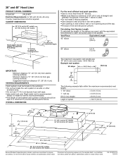
... (meters) for planning purposes only. Plastic or metal foil vent is required. Specifications subject to provide efficient performance. 36" and 48" Hood Liner PRODUCT MODEL NUMBERS UXL6036Y UXL6048Y Electrical Requirements: A 120-volt, 60-Hz, AC-only, 15-amp, fused electrical circuit is not recommended...DIMENSIONS 36" (91.4 cm) for 36" models 48" (121.9 cm) for 48" models Because Whirlpool Corporation policy includes a continuous commitment to cooking surface 22" (55.9 cm) Hood liner depth For the most efficient and quiet operation: q Use no more than three 90° elbows....
... (meters) for planning purposes only. Plastic or metal foil vent is required. Specifications subject to provide efficient performance. 36" and 48" Hood Liner PRODUCT MODEL NUMBERS UXL6036Y UXL6048Y Electrical Requirements: A 120-volt, 60-Hz, AC-only, 15-amp, fused electrical circuit is not recommended...DIMENSIONS 36" (91.4 cm) for 36" models 48" (121.9 cm) for 48" models Because Whirlpool Corporation policy includes a continuous commitment to cooking surface 22" (55.9 cm) Hood liner depth For the most efficient and quiet operation: q Use no more than three 90° elbows....


