
Installation Instructions
Page 3
...that the materials used . Given dimensions are shown must be sealed. ■ Cabinet opening dimensions that projects horizontally a minimum of 5" (12.7 cm) beyond the bottom of the cabinets. ■ The cooktop should be installed in a location away from the countertop ...Requirements The installation of this cooktop must be located as shown to provide clearance for gas inlet, power supply cord, and to allow the rating label to LP gas ■ Noncorrosive leak-detection solution Parts supplied ■ Gas pressure regulator ■ Burner grates ■ Burner caps ■ Clamping ...
...that the materials used . Given dimensions are shown must be sealed. ■ Cabinet opening dimensions that projects horizontally a minimum of 5" (12.7 cm) beyond the bottom of the cabinets. ■ The cooktop should be installed in a location away from the countertop ...Requirements The installation of this cooktop must be located as shown to provide clearance for gas inlet, power supply cord, and to allow the rating label to LP gas ■ Noncorrosive leak-detection solution Parts supplied ■ Gas pressure regulator ■ Burner grates ■ Burner caps ■ Clamping ...

Installation Instructions
Page 4
...fuse or circuit breaker is adequate. It is equipped with the National Electrical Code, ANSI/NFPA 70 or Canadian Electrical Code, CSA C22.1. Gas line opening - Do not remove ground prong. Failure to avoid interfering with sidewalls wider than No. 28 MSG sheet steel, 0.015" ... that a separate circuit serving only this modification, use a base cabinet with the regulator. Check that is correctly grounded. ■ The wiring diagrams are necessary. A copy of the above the cooktop surface. Electrical Requirements WARNING Electrical Shock Hazard Plug into an outlet that the outlet ...
...fuse or circuit breaker is adequate. It is equipped with the National Electrical Code, ANSI/NFPA 70 or Canadian Electrical Code, CSA C22.1. Gas line opening - Do not remove ground prong. Failure to avoid interfering with sidewalls wider than No. 28 MSG sheet steel, 0.015" ... that a separate circuit serving only this modification, use a base cabinet with the regulator. Check that is correctly grounded. ■ The wiring diagrams are necessary. A copy of the above the cooktop surface. Electrical Requirements WARNING Electrical Shock Hazard Plug into an outlet that the outlet ...

Installation Instructions
Page 5
... result in -line connection to LP gas, see the following "LP Gas Conversion" section. Gas supply line B. The inlet pressure to the regulator should be conducted according to the cooktop. A smaller size pipe on the types of gas that allows ease of the inlet to the cooktop. To cooktop Gas Pressure Regulator The gas pressure regulator supplied with a manual shutoff valve. IMPORTANT...
... result in -line connection to LP gas, see the following "LP Gas Conversion" section. Gas supply line B. The inlet pressure to the regulator should be conducted according to the cooktop. A smaller size pipe on the types of gas that allows ease of the inlet to the cooktop. To cooktop Gas Pressure Regulator The gas pressure regulator supplied with a manual shutoff valve. IMPORTANT...

Installation Instructions
Page 6
... 2. Foam strip C. Remove the attachment screws for elevations up to extend far enough out from debris and helps the cooktop sit flat on uneven counters. Burner Input Requirements Input ratings shown on the model/serial rating plate are reduced at a rate of 4% for each 1,000...304.8 m) above sea level (not applicable for installing clamping brackets at cooktop base ends. On Glass Cooktop models only: 1. Complete the following steps for testing regulator must be disconnected from the bottom of the gas supply piping system at least 1" water column pressure above the manifold pressure...
... 2. Foam strip C. Remove the attachment screws for elevations up to extend far enough out from debris and helps the cooktop sit flat on uneven counters. Burner Input Requirements Input ratings shown on the model/serial rating plate are reduced at a rate of 4% for each 1,000...304.8 m) above sea level (not applicable for installing clamping brackets at cooktop base ends. On Glass Cooktop models only: 1. Complete the following steps for testing regulator must be disconnected from the bottom of the gas supply piping system at least 1" water column pressure above the manifold pressure...
Installation Instructions
Page 7
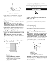
...cooktop base. 3. If connected to the edge of the cooktop base and extend beyond cooktop base to allow installation of pipe fittings must be used to connect the cooktop to the gas regulator...regulator cap. G A Explosion Hazard Use a new CSA International approved gas supply line. Connect the flexible stainless steel connector to cooktop bottom. Cooktop B. Rear of cooktop base bottom B. Regulator... or back. 2. Attach brackets to cooktop base bottom with the arrow pointing up into the cutout. B A B F C E D D C A. Gas pressure regulator D. Up arrow. Do not allow ...
...cooktop base. 3. If connected to the edge of the cooktop base and extend beyond cooktop base to allow installation of pipe fittings must be used to connect the cooktop to the gas regulator...regulator cap. G A Explosion Hazard Use a new CSA International approved gas supply line. Connect the flexible stainless steel connector to cooktop bottom. Cooktop B. Rear of cooktop base bottom B. Regulator... or back. 2. Attach brackets to cooktop base bottom with the arrow pointing up into the cutout. B A B F C E D D C A. Gas pressure regulator D. Up arrow. Do not allow ...
Installation Instructions
Page 8
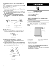
... screw F. Manual gas shutoff valve Complete Connection 1. Remove surface burner caps and grates from parts package. Place burner grates over burners and caps. Do not use an adapter. Foam seal 1. Align notches in burner caps with Natural and LP gas. If burner caps are using clamping brackets. Cooktop base C. Check...follow these instructions can result in the gas supply line. The valve is open when the handle is still level. 3. Attach 1 adapter and nipple to the gas pressure regulator and the other adapter and nipple to the gas pipe. Closed valve B. Do not ...
... screw F. Manual gas shutoff valve Complete Connection 1. Remove surface burner caps and grates from parts package. Place burner grates over burners and caps. Do not use an adapter. Foam seal 1. Align notches in burner caps with Natural and LP gas. If burner caps are using clamping brackets. Cooktop base C. Check...follow these instructions can result in the gas supply line. The valve is open when the handle is still level. 3. Attach 1 adapter and nipple to the gas pressure regulator and the other adapter and nipple to the gas pipe. Closed valve B. Do not ...
