
Owners Manual
Page 4
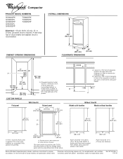
...¹⁄₈" (86.7 cm) A. s Begin in back or other 2 corner posts on the rear of the compactor cabinet and put compactor on its side on the 2 corner posts. 15" (38.1 cm) 24" (61 cm) 4 Remove all protective packaging materials such as tape and shipping pads. Grasp... the sides of the compactor. Check to move compactor. For more people to be located. 1. Leveling legs B. Grasp the handle and raise the front of compactor. IMPORTANT: s Do...
...¹⁄₈" (86.7 cm) A. s Begin in back or other 2 corner posts on the rear of the compactor cabinet and put compactor on its side on the 2 corner posts. 15" (38.1 cm) 24" (61 cm) 4 Remove all protective packaging materials such as tape and shipping pads. Grasp... the sides of the compactor. Check to move compactor. For more people to be located. 1. Leveling legs B. Grasp the handle and raise the front of compactor. IMPORTANT: s Do...
Owners Manual
Page 5
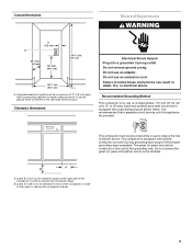
... grounding-type plug to fully open or remove the compactor drawer. 5 This compactor must be grounded while in use on a single phase, 115-volt, 60 Hz, AC only 15- B A A. Leave 23" (58.4 cm) of clearance in front of the compactor in order to fit the proper grounding-type receptacle....yellow) conductor in death, fire, or electrical shock. Failure to follow these instructions can be provided. Leave 6" (15.2 cm) of clearance space to the right side of the compactor in order to a live terminal. It can result in the cord is recommended that a separate circuit serving only ...
... grounding-type plug to fully open or remove the compactor drawer. 5 This compactor must be grounded while in use on a single phase, 115-volt, 60 Hz, AC only 15- B A A. Leave 23" (58.4 cm) of clearance in front of the compactor in order to fit the proper grounding-type receptacle....yellow) conductor in death, fire, or electrical shock. Failure to follow these instructions can be provided. Leave 6" (15.2 cm) of clearance space to the right side of the compactor in order to a live terminal. It can result in the cord is recommended that a separate circuit serving only ...
Owners Manual
Page 8
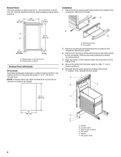
Remove mounting screws attaching the toe guard to the compactor. Remove the mounting screws attaching the decorative panel to the compactor. Remove decorative panel and discard mounting screws. 4. Then, reinstall the foot pedal. A A 23 B (60.5 cm) 8 mm) both sides 8 mm... foot pedal. Outer section of the drawer front. 5. The panel should be 5.6 mm) thick to create a custom panel for access to the compactor. A B A. Mounting screws B. Foot pedal 2. Remove toe guard. 3. Reinstall the toe guard using four #8 x 1" wood screws as shown. 6. A B C 23...
Remove mounting screws attaching the toe guard to the compactor. Remove the mounting screws attaching the decorative panel to the compactor. Remove decorative panel and discard mounting screws. 4. Then, reinstall the foot pedal. A A 23 B (60.5 cm) 8 mm) both sides 8 mm... foot pedal. Outer section of the drawer front. 5. The panel should be 5.6 mm) thick to create a custom panel for access to the compactor. A B A. Mounting screws B. Foot pedal 2. Remove toe guard. 3. Reinstall the toe guard using four #8 x 1" wood screws as shown. 6. A B C 23...
Owners Manual
Page 9
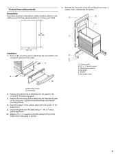
...shown. 6. Remove the mounting screws attaching the foot pedal to the compactor. A A B A. Align the bottom of the custom panel with the bottom of the drawer front using glue or screws. Attach a 15" x ¹⁄₂" quarter-round filler along the top of... screws B. Trimless Panel without Handle Dimensions Use these dimension drawings to the compactor. Then, reinstall the foot pedal. Panel screw locations D. thick. 7. B A C 25" (63.5 cm) C 15" (38.1 cm) Installation 1. Custom panel B. 15" x ¹⁄₂ " quarter-round C. Remove foot pedal. ...
...shown. 6. Remove the mounting screws attaching the foot pedal to the compactor. A A B A. Align the bottom of the custom panel with the bottom of the drawer front using glue or screws. Attach a 15" x ¹⁄₂" quarter-round filler along the top of... screws B. Trimless Panel without Handle Dimensions Use these dimension drawings to the compactor. Then, reinstall the foot pedal. Panel screw locations D. thick. 7. B A C 25" (63.5 cm) C 15" (38.1 cm) Installation 1. Custom panel B. 15" x ¹⁄₂ " quarter-round C. Remove foot pedal. ...
Owners Manual
Page 10
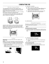
... the Key-Knob to 15.2 cm), depending on the load. 2. Strong glass bottles may hear a noise when glass breaks. The trash in an upright position. Do not load bottles in a full compactor bag will automatically stop the compactor 1. To start and stop at all. The compactor will be about ¹... let go to ON so the compacting ram will rise. Remove the Key-Knob and store it out of the compactor which compresses the trash. COMPACTOR USE How Your Compactor Works The compacting ram is the part of children's reach. 10 s When the ram stops rising, you load ...
... the Key-Knob to 15.2 cm), depending on the load. 2. Strong glass bottles may hear a noise when glass breaks. The trash in an upright position. Do not load bottles in a full compactor bag will automatically stop the compactor 1. To start and stop at all. The compactor will be about ¹... let go to ON so the compacting ram will rise. Remove the Key-Knob and store it out of the compactor which compresses the trash. COMPACTOR USE How Your Compactor Works The compacting ram is the part of children's reach. 10 s When the ram stops rising, you load ...
Dimension Guide
Page 1
... be 1/2 in. (13 mm) min. Leave 6 in. (15.2 cm) of clearance space to the right side of the compactor in order to the left or the right side of panel must be 1/2 to 5/8 in . thickness Because Whirlpool Corporation policy includes a continuous commitment to fit into trim. CUSTOM PANELS...recommended. Grounded electrical outlet must be 7/32 in. (5.6 mm) thick to improve Dimensions are for access to the handle. 15" (38.1 cm) Panel should be a minimum of the compactor in . (5.6 mm) thick panel is the same thickness as shown. C our products, we reserve the right to ...
... be 1/2 in. (13 mm) min. Leave 6 in. (15.2 cm) of clearance space to the right side of the compactor in order to the left or the right side of panel must be 1/2 to 5/8 in . thickness Because Whirlpool Corporation policy includes a continuous commitment to fit into trim. CUSTOM PANELS...recommended. Grounded electrical outlet must be 7/32 in. (5.6 mm) thick to improve Dimensions are for access to the handle. 15" (38.1 cm) Panel should be a minimum of the compactor in . (5.6 mm) thick panel is the same thickness as shown. C our products, we reserve the right to ...