Dimension Guide
Page 1
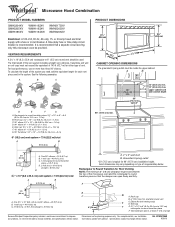
... vent system = 73 ft (22.2 m) total A B 6 ft (1.8 m) 66" (167.6 cm) min. 2 ft (0.6 m) C A. Exact dimensions may vary depending on type of vent. Roof cap B. 6" (15.2 cm) min. To calculate the length of the microwave oven and the rectangular to ... a separate circuit serving only this microwave oven be used in the system. Ref. A 2 ft (0.6 m) C A. Vent extension piece, at least 3" (7.6 cm) high Because Whirlpool Corporation policy includes a continuous commitment to round transition piece = 5 ft (1.5 m) D. 2 ft (0.6 m) + 6 ft (1.8 m) straight = 8 ft (2.4 m) D 3 ...
... vent system = 73 ft (22.2 m) total A B 6 ft (1.8 m) 66" (167.6 cm) min. 2 ft (0.6 m) C A. Exact dimensions may vary depending on type of vent. Roof cap B. 6" (15.2 cm) min. To calculate the length of the microwave oven and the rectangular to ... a separate circuit serving only this microwave oven be used in the system. Ref. A 2 ft (0.6 m) C A. Vent extension piece, at least 3" (7.6 cm) high Because Whirlpool Corporation policy includes a continuous commitment to round transition piece = 5 ft (1.5 m) D. 2 ft (0.6 m) + 6 ft (1.8 m) straight = 8 ft (2.4 m) D 3 ...

Installation Instructions
Page 1
... potential hazard is the safety alert symbol. Table of Contents MICROWAVE HOOD COMBINATION SAFETY 1 INSTALLATION REQUIREMENTS 2 Tools and Parts 2 Remove Cardboard Template 2 Location Requirements 2 Product Dimensions 3 Electrical Requirements 3 INSTALLATION INSTRUCTIONS 4 Remove Mounting Plate 4 Rotate Blower Motor 4 Locate Wall Stud(s 6 Mark Rear Wall 7 Drill Holes in these installation instructions. The appearance of...
... potential hazard is the safety alert symbol. Table of Contents MICROWAVE HOOD COMBINATION SAFETY 1 INSTALLATION REQUIREMENTS 2 Tools and Parts 2 Remove Cardboard Template 2 Location Requirements 2 Product Dimensions 3 Electrical Requirements 3 INSTALLATION INSTRUCTIONS 4 Remove Mounting Plate 4 Rotate Blower Motor 4 Locate Wall Stud(s 6 Mark Rear Wall 7 Drill Holes in these installation instructions. The appearance of...

Installation Instructions
Page 2
...or metal ■ No. 3 Phillips screwdriver for wall or roof venting. For other damages. Washers (2) D. Sheet metal screws (2) G. See "Installation Dimensions" illustration. ■ Minimum one 2" x 4" (50.8 x 101.6 mm) wood wall stud and minimum 3/8" (10 mm) thickness drywall or plaster/...freely and fully. Special Requirements For Wall Venting Installation Only: ■ Cutout must provide: ■ Minimum installation dimensions. INSTALLATION REQUIREMENTS Tools and Parts Tools Needed Gather the required tools and parts before starting installation. Check with any obstructions...
...or metal ■ No. 3 Phillips screwdriver for wall or roof venting. For other damages. Washers (2) D. Sheet metal screws (2) G. See "Installation Dimensions" illustration. ■ Minimum one 2" x 4" (50.8 x 101.6 mm) wood wall stud and minimum 3/8" (10 mm) thickness drywall or plaster/...freely and fully. Special Requirements For Wall Venting Installation Only: ■ Cutout must provide: ■ Minimum installation dimensions. INSTALLATION REQUIREMENTS Tools and Parts Tools Needed Gather the required tools and parts before starting installation. Check with any obstructions...

Installation Instructions
Page 3
.... Recommended: ■ A time-delay fuse or time-delay circuit breaker. ■ A separate circuit serving only this microwave oven. Exact dimensions may vary depending on type of electric shock. The plug must be grounded. In the event of an electrical short circuit, grounding reduces the...supply with a grounding plug. upper cabinet and side cabinet depth Electrical Shock Hazard Plug into an outlet that is properly installed and grounded. Product Dimensions 17¹⁄₄" (43.8 cm) 16¹⁄₄" (41.3 cm) (401.05³c⁄₄m") 29⁷⁄₈...
.... Recommended: ■ A time-delay fuse or time-delay circuit breaker. ■ A separate circuit serving only this microwave oven. Exact dimensions may vary depending on type of electric shock. The plug must be grounded. In the event of an electrical short circuit, grounding reduces the...supply with a grounding plug. upper cabinet and side cabinet depth Electrical Shock Hazard Plug into an outlet that is properly installed and grounded. Product Dimensions 17¹⁄₄" (43.8 cm) 16¹⁄₄" (41.3 cm) (401.05³c⁄₄m") 29⁷⁄₈...

Installation Instructions
Page 7
... holes are properly marked. Drill 3/4" (19 mm) holes through the mounting plate, closest to the centerline on both end holes. They must align with the dimensions described in Step 3 of cabinet. Set the mounting plate aside. This is level. 6. Refer to the horizontal line drawn in one 1/4-20 x 3" round-head bolt...
... holes are properly marked. Drill 3/4" (19 mm) holes through the mounting plate, closest to the centerline on both end holes. They must align with the dimensions described in Step 3 of cabinet. Set the mounting plate aside. This is level. 6. Refer to the horizontal line drawn in one 1/4-20 x 3" round-head bolt...

Installation Instructions
Page 8
... other hole drilled in Step 3 of the mounting plate. Push the 2 bolts with the holes in Rear Wall" section. 2. Make sure the 10" (25.4 cm) dimension from upper cabinet. 3. Insert lag screw(s) into the hole(s) drilled into the studs at both end holes. 3. Refer to open . Leave enough space for Wall...
... other hole drilled in Step 3 of the mounting plate. Push the 2 bolts with the holes in Rear Wall" section. 2. Make sure the 10" (25.4 cm) dimension from upper cabinet. 3. Insert lag screw(s) into the hole(s) drilled into the studs at both end holes. 3. Refer to open . Leave enough space for Wall...


