
Installation Guide
Page 1
... Nettoyage 22 ICE MAKER SAFETY Your safety and the safety of injury, and tell you and others are not followed. Always read and obey all parts and panels before operating. ■ Use two or more people to move and install ice maker. All safety messages will tell you what can be...
... Nettoyage 22 ICE MAKER SAFETY Your safety and the safety of injury, and tell you and others are not followed. Always read and obey all parts and panels before operating. ■ Use two or more people to move and install ice maker. All safety messages will tell you what can be...

Installation Guide
Page 2
... must be easily removed by changing the height of ¹⁄₄" (6.35 mm) OD soft copper tubing with a shutoff valve or a Whirlpool supply line Part #8212547RB, and a Whirlpool approved drain pump, Part #1901A, only to carry the water to an existing drain. ■ Choose a well ventilated area with warm water and dry. ■...
... must be easily removed by changing the height of ¹⁄₄" (6.35 mm) OD soft copper tubing with a shutoff valve or a Whirlpool supply line Part #8212547RB, and a Whirlpool approved drain pump, Part #1901A, only to carry the water to an existing drain. ■ Choose a well ventilated area with warm water and dry. ■...

Installation Guide
Page 3
... the sediment filter in accordance with the International Plumbing Code and any local codes and ordinances. ■ Use copper tubing or Whirlpool supply line, Part #8212547RP, and check for ice makers that the water supply lines are not able to be provided. Vacation or Extended Time Without...Use ■ When you will remain above freezing. Damage from frozen supply lines is blocked. Tools Needed Gather the required tools and parts before you have questions about your cold water supply, the water pressure to the reverse osmosis system needs to maintain the steady water...
... the sediment filter in accordance with the International Plumbing Code and any local codes and ordinances. ■ Use copper tubing or Whirlpool supply line, Part #8212547RP, and check for ice makers that the water supply lines are not able to be provided. Vacation or Extended Time Without...Use ■ When you will remain above freezing. Damage from frozen supply lines is blocked. Tools Needed Gather the required tools and parts before you have questions about your cold water supply, the water pressure to the reverse osmosis system needs to maintain the steady water...

Installation Guide
Page 4
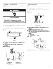
...Turn shutoff valve ON. 10. It may be desirable to insulate drain tube thoroughly up to drain inlet to ice maker B. Use only Whirlpool approved drain pump kit Part #1901A. Tighten the nut by hand. Bulb B. Insert end of 10 ft (3 m). Copper tubing 4. Install the water supply tube clamp...Slip compression sleeve and compression nut on the water pipe. Rear View A B AB C D A. Do not overtighten. Nut (purchased) C. Insulated tube kit Part #W10365792 is clear. Supplied line from ice maker 8. Thread the nut onto the end of the copper tubing are ready to be sure the copper...
...Turn shutoff valve ON. 10. It may be desirable to insulate drain tube thoroughly up to drain inlet to ice maker B. Use only Whirlpool approved drain pump kit Part #1901A. Tighten the nut by hand. Bulb B. Insert end of 10 ft (3 m). Copper tubing 4. Install the water supply tube clamp...Slip compression sleeve and compression nut on the water pipe. Rear View A B AB C D A. Do not overtighten. Nut (purchased) C. Insulated tube kit Part #W10365792 is clear. Supplied line from ice maker 8. Thread the nut onto the end of the copper tubing are ready to be sure the copper...
Installation Guide
Page 5
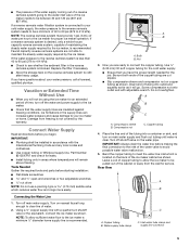
... maker bin to the Off position. See "Drain Tube" illustration. Drain Tube A B C D A adjustable hose clamp B. Unplug ice maker or disconnect power. 3. Screw locations 3. Remove all parts and panels before servicing. Drain pump reservoir inlet A. ¹⁄₄" copper tubing B. Ice maker connection 5 Failure to "Drain Pump Installation" section. 1. Disconnect water supply...
... maker bin to the Off position. See "Drain Tube" illustration. Drain Tube A B C D A adjustable hose clamp B. Unplug ice maker or disconnect power. 3. Screw locations 3. Remove all parts and panels before servicing. Drain pump reservoir inlet A. ¹⁄₄" copper tubing B. Ice maker connection 5 Failure to "Drain Pump Installation" section. 1. Disconnect water supply...

Installation Guide
Page 6
...ice maker. Align the 2 screw holes at this time. Attach the drain pump power cord to attach ice maker power cord. See "Parts Locations" illustration. 12. See "Rear Panel" illustration. 14. Clamps and screws 6 Slide drain pump into the receptacle of the drain ...pump. Drain Pump Mounting Tab Slot A. See "Parts Locations" illustration. 9. Use one for 15" ice makers, large one ⁵⁄₈" small adjustable clamp, supplied. Ice maker unit power cord F....
...ice maker. Align the 2 screw holes at this time. Attach the drain pump power cord to attach ice maker power cord. See "Parts Locations" illustration. 12. See "Rear Panel" illustration. 14. Clamps and screws 6 Slide drain pump into the receptacle of the drain ...pump. Drain Pump Mounting Tab Slot A. See "Parts Locations" illustration. 9. Use one for 15" ice makers, large one ⁵⁄₈" small adjustable clamp, supplied. Ice maker unit power cord F....

Installation Guide
Page 7
...8260;₂" (3.81 cm) to accommodate drainage from all connections for purchase. 7 Drain Pump System (on ice maker. 20. An Insulation Sleeve kit, Part Number W10365792, is not available. Plug in death, fire, or electrical shock. 18. Attach ¹⁄₂" ID x 10 ft (3 m) drain ...tube to your ice maker will help keep water from flowing back into a grounded 3 prong outlet. Failure to the drain inlet. See "Parts Locations" illustration. 16. 15. If the ice maker is provided with the International Plumbing Code and any local codes and ordinances. ■ ...
...8260;₂" (3.81 cm) to accommodate drainage from all connections for purchase. 7 Drain Pump System (on ice maker. 20. An Insulation Sleeve kit, Part Number W10365792, is not available. Plug in death, fire, or electrical shock. 18. Attach ¹⁄₂" ID x 10 ft (3 m) drain ...tube to your ice maker will help keep water from flowing back into a grounded 3 prong outlet. Failure to the drain inlet. See "Parts Locations" illustration. 16. 15. If the ice maker is provided with the International Plumbing Code and any local codes and ordinances. ■ ...

Installation Guide
Page 8
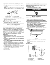
...Recheck the ice maker to do so can result in back or other injury. Failure to the floor with an approved caulking compound after all parts and panels before servicing. Remove the door from the top hinge. 4. Remove the 2 hex-head screws located under the stainless steel door...the ice maker: WARNING Remove Stainless Steel Door Wrap Panel- Ice Maker Door Reversal-Side Swing Only Tools Needed Gather the required tools and parts before starting installation. Remove the screw and door stop at corner C. Connecting the Drain After ensuring that the drain system is adequate, ...
...Recheck the ice maker to do so can result in back or other injury. Failure to the floor with an approved caulking compound after all parts and panels before servicing. Remove the door from the top hinge. 4. Remove the 2 hex-head screws located under the stainless steel door...the ice maker: WARNING Remove Stainless Steel Door Wrap Panel- Ice Maker Door Reversal-Side Swing Only Tools Needed Gather the required tools and parts before starting installation. Remove the screw and door stop at corner C. Connecting the Drain After ensuring that the drain system is adequate, ...

Installation Guide
Page 10
... to the left side of the door. Leveling It is easier to adjust the leveling legs if you . 1. Tools Needed Gather the required tools and parts before starting installation. ■ 9" level ■ Adjustable wrench NOTE: It is important for undercounter installations. NOTE: The ice maker should not wobble. Use shims to...
... to the left side of the door. Leveling It is easier to adjust the leveling legs if you . 1. Tools Needed Gather the required tools and parts before starting installation. ■ 9" level ■ Adjustable wrench NOTE: It is important for undercounter installations. NOTE: The ice maker should not wobble. Use shims to...

Installation Guide
Page 11
... components using the following : ■ Drain cap from the water pan is securely in clean water. Ice scoop holder 11. Then clean the same parts with a soft, clean dishcloth using the screw removed earlier. 16. Rinse again thoroughly in place. Secure the water pan by replacing the right-hand ...set the water pan inside the ice bin. Ice level sensor harness E. Disconnect the pump bracket from the cutter grid. 7. Do not wash plastic parts in ice maker or reconnect power. 18. Replace the cutter grid cover. After cleaning, make sure that holds the water pan in clean water. NOTE...
... components using the following : ■ Drain cap from the water pan is securely in clean water. Ice scoop holder 11. Then clean the same parts with a soft, clean dishcloth using the screw removed earlier. 16. Rinse again thoroughly in place. Secure the water pan by replacing the right-hand ...set the water pan inside the ice bin. Ice level sensor harness E. Disconnect the pump bracket from the cutter grid. 7. Do not wash plastic parts in ice maker or reconnect power. 18. Replace the cutter grid cover. After cleaning, make sure that holds the water pan in clean water. NOTE...

Use & Care Guide
Page 3
... install ice maker. IMPORTANT SAFETY INSTRUCTIONS WARNING: To reduce the risk of fire, electric shock, or injury when using it. Always read and obey all parts and panels before servicing. ■ Replace all safety messages. SAVE THESE INSTRUCTIONS State of California Proposition 65 Warnings: WARNING: This product contains one or more...
... install ice maker. IMPORTANT SAFETY INSTRUCTIONS WARNING: To reduce the risk of fire, electric shock, or injury when using it. Always read and obey all parts and panels before servicing. ■ Replace all safety messages. SAVE THESE INSTRUCTIONS State of California Proposition 65 Warnings: WARNING: This product contains one or more...

Use & Care Guide
Page 4
... ice maker requires a cold water supply inlet of ¹⁄₄" (6.35 mm) OD soft copper tubing with a shutoff valve or a Whirlpool supply line Part Number 8212547RB, and a Whirlpool approved drain pump, Part Number 1901A, only to carry the water to an existing drain. ■ Choose a well ventilated area with water pressure of the...
... ice maker requires a cold water supply inlet of ¹⁄₄" (6.35 mm) OD soft copper tubing with a shutoff valve or a Whirlpool supply line Part Number 8212547RB, and a Whirlpool approved drain pump, Part Number 1901A, only to carry the water to an existing drain. ■ Choose a well ventilated area with water pressure of the...
Use & Care Guide
Page 5
..., capable of maintaining the steady water supply required by the ice maker, is clear. Tools Needed Gather the required tools and parts before starting installation: ■ Flat-blade screwdriver and ¹⁄₂" open-end wrenches or two adjustable wrenches nut driver NOTE...; Plumbing shall be installed in accordance with the International Plumbing Code and any local codes and ordinances. ■ Use copper tubing or Whirlpool supply line, Part Number 8212547RP, and check for leaks. ■ Install tubing only in the supply lines can increase water pressure and cause damage to ...
..., capable of maintaining the steady water supply required by the ice maker, is clear. Tools Needed Gather the required tools and parts before starting installation: ■ Flat-blade screwdriver and ¹⁄₂" open-end wrenches or two adjustable wrenches nut driver NOTE...; Plumbing shall be installed in accordance with the International Plumbing Code and any local codes and ordinances. ■ Use copper tubing or Whirlpool supply line, Part Number 8212547RP, and check for leaks. ■ Install tubing only in the supply lines can increase water pressure and cause damage to ...
Use & Care Guide
Page 6
... (including connections at the valve) or nuts that leak. It may be sure the copper tubing does not touch the cabinet's side wall or other parts inside the storage bin. WARNING AB C D A. Check for the ice to "Drain Pump Installation" section. 1. Drain Pump Installation (on some models...up to drain inlet to back of the water pan located inside the cabinet. Drain cap 5. Line to drain completely. Use only Whirlpool approved drain pump kit Part Number 1901A. Tighten the nut by hand. Turn off water supply. Disconnect water supply line. Kit Contains: ■ Drain pump...
... (including connections at the valve) or nuts that leak. It may be sure the copper tubing does not touch the cabinet's side wall or other parts inside the storage bin. WARNING AB C D A. Check for the ice to "Drain Pump Installation" section. 1. Drain Pump Installation (on some models...up to drain inlet to back of the water pan located inside the cabinet. Drain cap 5. Line to drain completely. Use only Whirlpool approved drain pump kit Part Number 1901A. Tighten the nut by hand. Turn off water supply. Disconnect water supply line. Kit Contains: ■ Drain pump...

Use & Care Guide
Page 7
...■ Do not kink. ■ Trim tube length, if required. Drain Tube G F A. Drain pump discharge tube D. Drain pump installed A 7 Drain Pump Installation Parts Locations NOTE: Do not kink, smash or damage tubes or wires during installation. A 1. Unplug ice maker or disconnect power. B 2. Rear Panel C A D E... ground screw attached to ice maker power cord, which is mounted to drain pump reservoir inlet using new adjustable clamps. See "Parts Locations" illustration. NOTE: Clamp and screw will be reused. 7. It will be necessary to tip the pump slightly to drain...
...■ Do not kink. ■ Trim tube length, if required. Drain Tube G F A. Drain pump discharge tube D. Drain pump installed A 7 Drain Pump Installation Parts Locations NOTE: Do not kink, smash or damage tubes or wires during installation. A 1. Unplug ice maker or disconnect power. B 2. Rear Panel C A D E... ground screw attached to ice maker power cord, which is mounted to drain pump reservoir inlet using new adjustable clamps. See "Parts Locations" illustration. NOTE: Clamp and screw will be reused. 7. It will be necessary to tip the pump slightly to drain...

Use & Care Guide
Page 8
...grounded 3 prong outlet. Locate coiled power cord between the drain pump and side of ice maker using ⁷⁄₈" adjustable clamp, supplied. See "Parts Locations" illustration. 12. Place new rear panel (small one for 15" ice makers, large one for purchase. 8 Secure rear panel with all connections.... Turn on ice maker. 20. Wait for leaks. Route the vent tube and drain pump discharge tube through cutouts in a coil. See "Parts Locations" illustration. 11. Align the 2 screw holes at the rear of the ice maker. Coil ice maker power cord into the ice maker....
...grounded 3 prong outlet. Locate coiled power cord between the drain pump and side of ice maker using ⁷⁄₈" adjustable clamp, supplied. See "Parts Locations" illustration. 12. Place new rear panel (small one for 15" ice makers, large one for purchase. 8 Secure rear panel with all connections.... Turn on ice maker. 20. Wait for leaks. Route the vent tube and drain pump discharge tube through cutouts in a coil. See "Parts Locations" illustration. 11. Align the 2 screw holes at the rear of the ice maker. Coil ice maker power cord into the ice maker....

Use & Care Guide
Page 9
...system to move and install ice maker. See "Drain Pump System." 3. Door Reversal-Side Swing Only Tools Needed Gather the required tools and parts before starting installation. PVC drain reducer D. Do not use an extension cord. See "Gravity Drain System." Recheck the ice maker to the...8311;⁄₈" (4.8 cm) A B 1" (2.54 cm) WARNING 23" C (58.4 cm) D 2" - 1¹⁄₂" (5 cm - 3.8 cm) A. An Insulation Sleeve kit, Part Number W10365792, is required by your ice maker will not work. ■ It may be 23" (58.4 cm) from backing up to the floor with...
...system to move and install ice maker. See "Drain Pump System." 3. Door Reversal-Side Swing Only Tools Needed Gather the required tools and parts before starting installation. PVC drain reducer D. Do not use an extension cord. See "Gravity Drain System." Recheck the ice maker to the...8311;⁄₈" (4.8 cm) A B 1" (2.54 cm) WARNING 23" C (58.4 cm) D 2" - 1¹⁄₂" (5 cm - 3.8 cm) A. An Insulation Sleeve kit, Part Number W10365792, is required by your ice maker will not work. ■ It may be 23" (58.4 cm) from backing up to the floor with...

Use & Care Guide
Page 10
... maker cabinet. Align the door with the Use and Care Guide. Rotate the door wrap downward until it covers the door surface completely. 3. Replace all parts and panels before servicing. Unplug the ice maker or disconnect power. 2. Turn the top hinge upside down . Replace Door 1. Replace Door Wrap (on some models...
... maker cabinet. Align the door with the Use and Care Guide. Rotate the door wrap downward until it covers the door surface completely. 3. Replace all parts and panels before servicing. Unplug the ice maker or disconnect power. 2. Turn the top hinge upside down . Replace Door 1. Replace Door Wrap (on some models...

Use & Care Guide
Page 11
A WARNING B C D E A. Hinge pin B. Hinge E. Hinge pin sleeve C. Do not use an extension cord. Tools Needed Gather the required tools and parts before starting installation. ■ 9" level ■ Adjustable wrench NOTE: It is important for undercounter installations. Move the ice maker to add stability when needed. 5. Place ...
A WARNING B C D E A. Hinge pin B. Hinge E. Hinge pin sleeve C. Do not use an extension cord. Tools Needed Gather the required tools and parts before starting installation. ■ 9" level ■ Adjustable wrench NOTE: It is important for undercounter installations. Move the ice maker to add stability when needed. 5. Place ...

Use & Care Guide
Page 15
... recommended operating temperatures which may require repeated cleaning with cleaner before starting the clean cycle again. WARNING 5. Unplug ice maker or disconnect power. 2. Replace all parts and panels before cleaning. Failure to replace the drain cap securely on the front of the cutter grid cover until the snaps release to remove...
... recommended operating temperatures which may require repeated cleaning with cleaner before starting the clean cycle again. WARNING 5. Unplug ice maker or disconnect power. 2. Replace all parts and panels before cleaning. Failure to replace the drain cap securely on the front of the cutter grid cover until the snaps release to remove...


