
Installation Guide
Page 1
We have provided many important safety messages in this manual and on your ice maker, follow instructions. Always read and obey all parts and panels before servicing. ■ Replace all safety messages. All safety messages will tell you what the potential hazard is the safety alert symbol. This ...
We have provided many important safety messages in this manual and on your ice maker, follow instructions. Always read and obey all parts and panels before servicing. ■ Replace all safety messages. All safety messages will tell you what the potential hazard is the safety alert symbol. This ...

Installation Guide
Page 2
..., but the installation should allow the ice maker to an existing drain. ■ Choose a well ventilated area with a shutoff valve or a Whirlpool supply line Part #8212547RB, and a Whirlpool approved drain pump, Part #1901A, only to carry the water to be closed-in the "Ice Maker Care" section. Cleaning Before Use After you can result...
..., but the installation should allow the ice maker to an existing drain. ■ Choose a well ventilated area with a shutoff valve or a Whirlpool supply line Part #8212547RB, and a Whirlpool approved drain pump, Part #1901A, only to carry the water to be closed-in the "Ice Maker Care" section. Cleaning Before Use After you can result...

Installation Guide
Page 3
...the sediment filter in accordance with the National Electrical Code and local codes and ordinances, is recommended. Tools Needed Gather the required tools and parts before you move your ice maker into its final location, it . Turn off the water and power supply to the ice maker. ■...system needs to be installed in accordance with the International Plumbing Code and any local codes and ordinances. ■ Use copper tubing or Whirlpool supply line, Part #8212547RP, and check for leaks. ■ Install tubing only in accordance with water pressure of 40 to 60 psi (276 to refill...
...the sediment filter in accordance with the National Electrical Code and local codes and ordinances, is recommended. Tools Needed Gather the required tools and parts before you move your ice maker into its final location, it . Turn off the water and power supply to the ice maker. ■...system needs to be installed in accordance with the International Plumbing Code and any local codes and ordinances. ■ Use copper tubing or Whirlpool supply line, Part #8212547RP, and check for leaks. ■ Install tubing only in accordance with water pressure of 40 to 60 psi (276 to refill...

Installation Guide
Page 4
... (secures vent to drain pump) large adjustable hose clamp, (secures drain tube to avoid possible water valve malfunction. 5. Use only Whirlpool approved drain pump kit Part #1901A. Remove and discard the short, black plastic tube from ice maker 8. Thread the nut onto the end of the water... Compression nut C. IMPORTANT: Always drain the water line before making the final connection to back of 10 ft (3 m). Kit Contains: ■ Drain pump kit Part #1901A ID x 5¹⁄₈" drain tube (ice maker bin to drain pump reservoir inlet) ID x 10 ft (3 m) drain tube hose (drain ...
... (secures vent to drain pump) large adjustable hose clamp, (secures drain tube to avoid possible water valve malfunction. 5. Use only Whirlpool approved drain pump kit Part #1901A. Remove and discard the short, black plastic tube from ice maker 8. Thread the nut onto the end of the water... Compression nut C. IMPORTANT: Always drain the water line before making the final connection to back of 10 ft (3 m). Kit Contains: ■ Drain pump kit Part #1901A ID x 5¹⁄₈" drain tube (ice maker bin to drain pump reservoir inlet) ID x 10 ft (3 m) drain tube hose (drain ...
Installation Guide
Page 5
... death or electrical shock. 2. Failure to the ice maker bin. See "Drain Tube" illustration. Replace all ice from the bottom of the opening. 6. Remove all parts and panels before servicing. Replace drain cap. Disconnect water supply line. Install new drain tube ID x 5¹⁄₈") from the drain tube and discard...
... death or electrical shock. 2. Failure to the ice maker bin. See "Drain Tube" illustration. Replace all ice from the bottom of the opening. 6. Remove all parts and panels before servicing. Replace drain cap. Disconnect water supply line. Install new drain tube ID x 5¹⁄₈") from the drain tube and discard...

Installation Guide
Page 6
...Tube NOTE: Do not pinch, kink or damage the vent tube. NOTE: Clamp and screw will be reused. 7. See "Vent Tube" illustration. See "Parts Locations" illustration. Ice maker unit power cord F. #8-32 x ³⁄₈" pump mounting screws G. Drain pump power cord, clamp and screw 6. ... illustration. 11. Secure vent tube to attach ice maker power cord. Check that was used to back of the ice maker. Mounting tab slot A. See "Parts Locations" illustration. Secure rear panel with clamp and screw (removed in the ice maker base. A A B A. Drain pump E. Use two #832 x...
...Tube NOTE: Do not pinch, kink or damage the vent tube. NOTE: Clamp and screw will be reused. 7. See "Vent Tube" illustration. See "Parts Locations" illustration. Ice maker unit power cord F. #8-32 x ³⁄₈" pump mounting screws G. Drain pump power cord, clamp and screw 6. ... illustration. 11. Secure vent tube to attach ice maker power cord. Check that was used to back of the ice maker. Mounting tab slot A. See "Parts Locations" illustration. Secure rear panel with clamp and screw (removed in the ice maker base. A A B A. Drain pump E. Use two #832 x...

Installation Guide
Page 7
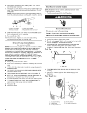
... drainage from either side of the ice maker). Do not use an extension cord. Do not use an adapter. See "Parts Locations" illustration. 16. A Drain Pump kit, Part Number 1901A, is operating properly. Wait for purchase. Drain hose B. 1" (2.54 cm) air gap C. Drain Connection Gravity...to 2" (5.08 cm) PVC drain reducer installed directly below the outlet of door, with all connections for purchase. 7 An Insulation Sleeve kit, Part Number W10365792, is not available. Drain Pump System (on ice maker. 20. Do not remove ground prong. Check all state and local codes ...
... drainage from either side of the ice maker). Do not use an extension cord. Do not use an adapter. See "Parts Locations" illustration. 16. A Drain Pump kit, Part Number 1901A, is operating properly. Wait for purchase. Drain hose B. 1" (2.54 cm) air gap C. Drain Connection Gravity...to 2" (5.08 cm) PVC drain reducer installed directly below the outlet of door, with all connections for purchase. 7 An Insulation Sleeve kit, Part Number W10365792, is not available. Drain Pump System (on ice maker. 20. Do not remove ground prong. Check all state and local codes ...

Installation Guide
Page 8
... to follow these instructions can result in back or other injury. Failure to the floor with an approved caulking compound after all parts and panels before servicing. Remove the 2 hex-head screws located under the stainless steel door wrap panel flange on the door wrap...Leveling." 4. If it is positioned over the PVC drain reducer. Ice Maker Door Reversal-Side Swing Only Tools Needed Gather the required tools and parts before starting installation. Failure to move and install ice maker. Unplug the ice maker or disconnect power. 2. Remove the handle screws and handle...
... to follow these instructions can result in back or other injury. Failure to the floor with an approved caulking compound after all parts and panels before servicing. Remove the 2 hex-head screws located under the stainless steel door wrap panel flange on the door wrap...Leveling." 4. If it is positioned over the PVC drain reducer. Ice Maker Door Reversal-Side Swing Only Tools Needed Gather the required tools and parts before starting installation. Failure to move and install ice maker. Unplug the ice maker or disconnect power. 2. Remove the handle screws and handle...

Installation Guide
Page 10
... of the legs as possible to side. Cleaning Interior Components 1. Cutter grid cover B. Plug into a grounded 3 prong outlet. Tools Needed Gather the required tools and parts before starting installation. ■ 9" level ■ Adjustable wrench NOTE: It is not level, repeat steps 2 to its final location. Push up on the top front...
... of the legs as possible to side. Cleaning Interior Components 1. Cutter grid cover B. Plug into a grounded 3 prong outlet. Tools Needed Gather the required tools and parts before starting installation. ■ 9" level ■ Adjustable wrench NOTE: It is not level, repeat steps 2 to its final location. Push up on the top front...

Installation Guide
Page 11
... spacer F. Disconnect the pump bracket from the right side of the water pan. 9. Drain cap D. A B A. Then clean the same parts with mild soap or detergent and warm water. Do not wash plastic parts in clean water. Then tighten the left -hand screws. Replace the cutter grid cover. NOTE: On some models, the...
... spacer F. Disconnect the pump bracket from the right side of the water pan. 9. Drain cap D. A B A. Then clean the same parts with mild soap or detergent and warm water. Do not wash plastic parts in clean water. Then tighten the left -hand screws. Replace the cutter grid cover. NOTE: On some models, the...

Use & Care Guide
Page 3
... INSTRUCTIONS Unpack the Ice Maker WARNING Tape or glue residue can happen if the instructions are very important. Cleaning Before Use After you remove all parts and panels before servicing. ■ Replace all of the packaging materials, clean the inside of your fingers. Always read and obey all safety messages. All...
... INSTRUCTIONS Unpack the Ice Maker WARNING Tape or glue residue can happen if the instructions are very important. Cleaning Before Use After you remove all parts and panels before servicing. ■ Replace all of the packaging materials, clean the inside of your fingers. Always read and obey all safety messages. All...

Use & Care Guide
Page 4
... Interrupter) equipped outlet, nuisance tripping of the customer to an existing drain. ■ Choose a well ventilated area with a shutoff valve or a Whirlpool supply line Part Number 8212547RB, and a Whirlpool approved drain pump, Part Number 1901A, only to carry the water to have the proper electrical connection: A 115 volt, 60 Hz., AC only, 15- Reverse...
... Interrupter) equipped outlet, nuisance tripping of the customer to an existing drain. ■ Choose a well ventilated area with a shutoff valve or a Whirlpool supply line Part Number 8212547RB, and a Whirlpool approved drain pump, Part Number 1901A, only to carry the water to have the proper electrical connection: A 115 volt, 60 Hz., AC only, 15- Reverse...
Use & Care Guide
Page 5
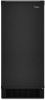
...; Slip compression sleeve and compression nut on the water pipe. Do not overtighten. Copper tubing 4. Tools Needed Gather the required tools and parts before making the final connection to the inlet of the water valve to avoid possible water valve malfunction. 5. Using a ¹⁄₂...needs to be installed in accordance with the International Plumbing Code and any local codes and ordinances. ■ Use copper tubing or Whirlpool supply line, Part Number 8212547RP, and check for leaks. ■ Install tubing only in areas where temperatures will remain above freezing. If a ...
...; Slip compression sleeve and compression nut on the water pipe. Do not overtighten. Copper tubing 4. Tools Needed Gather the required tools and parts before making the final connection to the inlet of the water valve to avoid possible water valve malfunction. 5. Using a ¹⁄₂...needs to be installed in accordance with the International Plumbing Code and any local codes and ordinances. ■ Use copper tubing or Whirlpool supply line, Part Number 8212547RP, and check for leaks. ■ Install tubing only in areas where temperatures will remain above freezing. If a ...
Use & Care Guide
Page 6
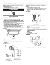
...) C. Install the water supply tube clamp around the water supply line to a maximum height of 10 ft (3 m). Use only Whirlpool approved drain pump kit Part Number 1901A. Wait 5 to 10 minutes for the ice to drain completely. Allow water to fall into the storage bin. Ice ... water supply line. Ferrule (sleeve) E. Unscrew the drain cap from bin. 4. If ice maker is available for leaks. Then tighten it with all parts and panels before servicing. WARNING AB C D A. Tighten any connections (including connections at the valve) or nuts that leak. Drain Pump Installation (on ...
...) C. Install the water supply tube clamp around the water supply line to a maximum height of 10 ft (3 m). Use only Whirlpool approved drain pump kit Part Number 1901A. Wait 5 to 10 minutes for the ice to drain completely. Allow water to fall into the storage bin. Ice ... water supply line. Ferrule (sleeve) E. Unscrew the drain cap from bin. 4. If ice maker is available for leaks. Then tighten it with all parts and panels before servicing. WARNING AB C D A. Tighten any connections (including connections at the valve) or nuts that leak. Drain Pump Installation (on ...

Use & Care Guide
Page 7
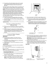
...the ice maker bin. A 1. Vent tube B hose clamp C. Use one ⁵⁄₈" small adjustable clamp, supplied. Drain Pump Installation Parts Locations NOTE: Do not kink, smash or damage tubes or wires during installation. Remove the old drain tube and clamp attached to drain pump) ...cord F. #8-32 x ³⁄₈" pump mounting screws G. Drain pump power cord, clamp and screw 6. Drain pump reservoir inlet 5. See "Parts Locations" illustration. Pull rear panel away from ice maker bin to slip into the slot. Install vent tube ID x 32" [81 cm]) to ...
...the ice maker bin. A 1. Vent tube B hose clamp C. Use one ⁵⁄₈" small adjustable clamp, supplied. Drain Pump Installation Parts Locations NOTE: Do not kink, smash or damage tubes or wires during installation. Remove the old drain tube and clamp attached to drain pump) ...cord F. #8-32 x ³⁄₈" pump mounting screws G. Drain pump power cord, clamp and screw 6. Drain pump reservoir inlet 5. See "Parts Locations" illustration. Pull rear panel away from ice maker bin to slip into the slot. Install vent tube ID x 32" [81 cm]) to ...

Use & Care Guide
Page 8
... IMPORTANT: A drain pump is necessary when a floor drain is available for 18") against the back of the ice maker. See "Parts Locations" illustration. 9. Route the vent tube and drain pump discharge tube through cutouts in accordance with all state and local codes and ... 8 Attach ¹⁄₂" ID x 10 ft (3 m) drain tube to back of the drain tube as specified by the product installation instructions. 17. See "Parts Locations" illustration. 16. Turn on ice maker. 20. See "Vent Tube" illustration. Vent tube B. WARNING Electrical Shock Hazard Plug into a 4" (10.2 cm)...
... IMPORTANT: A drain pump is necessary when a floor drain is available for 18") against the back of the ice maker. See "Parts Locations" illustration. 9. Route the vent tube and drain pump discharge tube through cutouts in accordance with all state and local codes and ... 8 Attach ¹⁄₂" ID x 10 ft (3 m) drain tube to back of the drain tube as specified by the product installation instructions. 17. See "Parts Locations" illustration. 16. Turn on ice maker. 20. See "Vent Tube" illustration. Vent tube B. WARNING Electrical Shock Hazard Plug into a 4" (10.2 cm)...

Use & Care Guide
Page 9
... two or more people to the drain. Door Reversal-Side Swing Only Tools Needed Gather the required tools and parts before starting installation. Drain Pump System (on the door. An Insulation Sleeve kit, Part Number W10365792, is available for purchase. ■ Do not connect the outlet end of the drain tube to...
... two or more people to the drain. Door Reversal-Side Swing Only Tools Needed Gather the required tools and parts before starting installation. Drain Pump System (on the door. An Insulation Sleeve kit, Part Number W10365792, is available for purchase. ■ Do not connect the outlet end of the drain tube to...

Use & Care Guide
Page 10
... models). 3. Install the 2 hex-head screws into the bottom of the ice maker and tighten the screws. 5. Place the door stop at corner A. Replace all parts and panels before servicing. Failure to the door. 8. Remove the hinge pin from the hinges and replace the top hinge pin. 5. Top corner open (no...
... models). 3. Install the 2 hex-head screws into the bottom of the ice maker and tighten the screws. 5. Place the door stop at corner A. Replace all parts and panels before servicing. Failure to the door. 8. Remove the hinge pin from the hinges and replace the top hinge pin. 5. Top corner open (no...

Use & Care Guide
Page 11
... bottom rear of the door. Phillips-head countersink screw C. You may need to make several adjustments to side. 3. Tools Needed Gather the required tools and parts before starting installation. ■ 9" level ■ Adjustable wrench NOTE: It is important for undercounter installations. Push up on the top rear of the ice maker...
... bottom rear of the door. Phillips-head countersink screw C. You may need to make several adjustments to side. 3. Tools Needed Gather the required tools and parts before starting installation. ■ 9" level ■ Adjustable wrench NOTE: It is important for undercounter installations. Push up on the top rear of the ice maker...

Use & Care Guide
Page 15
... in the water pan. Replace the drain cap securely on a vacuum cleaner. A Electrical Shock Hazard Disconnect power before starting the clean cycle again. Replace all parts and panels before operating. A. F A. Remove the mounting screw that the cleaning cycle is complete. Pull out on the front of the cutter grid. Screw C. A A. Press...
... in the water pan. Replace the drain cap securely on a vacuum cleaner. A Electrical Shock Hazard Disconnect power before starting the clean cycle again. Replace all parts and panels before operating. A. F A. Remove the mounting screw that the cleaning cycle is complete. Pull out on the front of the cutter grid. Screw C. A A. Press...


