Dimension Guide
Page 1
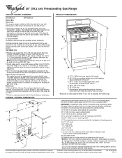
... and materials used for use with a different gas without consulting the serving gas supplier. Model/serial rating plate (located on or shutting off gas to the range opening dimensions shown are for dimensional clearances above the range, follow the range hood or microwave hood combination installation instructions for planning purposes only. E. 30¹⁄₈" (76.5 cm) min...
... and materials used for use with a different gas without consulting the serving gas supplier. Model/serial rating plate (located on or shutting off gas to the range opening dimensions shown are for dimensional clearances above the range, follow the range hood or microwave hood combination installation instructions for planning purposes only. E. 30¹⁄₈" (76.5 cm) min...
Installation Guide
Page 3
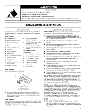
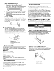
... it conforms to follow the instructions provided with local codes. Tools needed Check local codes and consult gas supplier. Any method of securing the range is the installer's responsibility to the floor during transit. WARNING Tip Over Hazard A child or adult... bracket B. Mobile Home - When such standard is located on the model/serial rating plate. INSTALLATION REQUIREMENTS Tools and Parts Gather the required tools and parts before starting installation. A B C A. See "Gas Supply Requirements" section. ■ Contact a qualified floor covering installer to the...
... it conforms to follow the instructions provided with local codes. Tools needed Check local codes and consult gas supplier. Any method of securing the range is the installer's responsibility to the floor during transit. WARNING Tip Over Hazard A child or adult... bracket B. Mobile Home - When such standard is located on the model/serial rating plate. INSTALLATION REQUIREMENTS Tools and Parts Gather the required tools and parts before starting installation. A B C A. See "Gas Supply Requirements" section. ■ Contact a qualified floor covering installer to the...

Installation Guide
Page 4
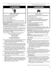
...cm) J. 2" (5.1 cm) K. 4¹⁄₂" (11.4 cm) L. 2" (5.1 cm) min. E. 30¹⁄₈" (76.5 cm) min. M. Grounded outlet N. Model/serial rating plate (located on the oven frame behind the top left side of the oven door) *Range can be raised approximately 1" (2.5 cm) by not less than ¹⁄₄" (0.64... recommended for installation of range to side wall or other combustible material. clearance from both sides of rigid gas pipe. opening width F. The shaded areas are for dimensional clearances above the range, follow the range hood or microwave hood ...
...cm) J. 2" (5.1 cm) K. 4¹⁄₂" (11.4 cm) L. 2" (5.1 cm) min. E. 30¹⁄₈" (76.5 cm) min. M. Grounded outlet N. Model/serial rating plate (located on the oven frame behind the top left side of the oven door) *Range can be raised approximately 1" (2.5 cm) by not less than ¹⁄₄" (0.64... recommended for installation of range to side wall or other combustible material. clearance from both sides of rigid gas pipe. opening width F. The shaded areas are for dimensional clearances above the range, follow the range hood or microwave hood ...
Installation Guide
Page 5
...use with a qualified electrician if you not plug an electric spark ignition gas range or any other major appliance into a GFCI wall outlet as to whether the metal chassis of the range is located on the model/serial rating plate for use with the National Electrical Code, ANSI/NFPA 70 or... Canadian Electrical Code, CSA C22.1. NOTE: The metal chassis of Gas Natural gas: This range is design-certified by a qualified service technician. ...
...use with a qualified electrician if you not plug an electric spark ignition gas range or any other major appliance into a GFCI wall outlet as to whether the metal chassis of the range is located on the model/serial rating plate for use with the National Electrical Code, ANSI/NFPA 70 or... Canadian Electrical Code, CSA C22.1. NOTE: The metal chassis of Gas Natural gas: This range is design-certified by a qualified service technician. ...
Installation Guide
Page 6
... legs one -half turn . Rear leveling leg C. B Gas Supply Pressure Testing Gas supply pressure for testing regulator must be at a rate of 4% for each 1,000 ft (304.8 m) above ½ psi gauge (14" WCP) The range and its individual manual shutoff valve during any pressure testing of... -half turn . All strains must be used . A C A. Remove oven racks and parts package from range. 2. Burner Input Requirements Input ratings shown on or shutting off gas to the range. Line pressure testing above sea level (not applicable for connection to the female pipe threads of ½ psi...
... legs one -half turn . Rear leveling leg C. B Gas Supply Pressure Testing Gas supply pressure for testing regulator must be at a rate of 4% for each 1,000 ft (304.8 m) above ½ psi gauge (14" WCP) The range and its individual manual shutoff valve during any pressure testing of... -half turn . All strains must be used . A C A. Remove oven racks and parts package from range. 2. Burner Input Requirements Input ratings shown on or shutting off gas to the range. Line pressure testing above sea level (not applicable for connection to the female pipe threads of ½ psi...
Installation Guide
Page 14
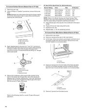
... one of spuds for proper sizing of the screws through the range cooktop to hold the gas orifice spud in place while removing and replacing the orifice spuds. Set gas orifice spud aside. C A D B A. LP Gas Orifice Spud Chart for Surface Burners Burner Rating Color Size ID Number 14,000 BTU 11,000 BTU 8,000... spud with 1 color dot, and have a groove in the cardboard orifice spud holder. 6. Remove 2 screws at the rear of the range near the gas inlet. Igniter electrode B. Burner cap D. Lift the rear of the oven bottom up and back until the front of oven and set it ...
... one of spuds for proper sizing of the screws through the range cooktop to hold the gas orifice spud in place while removing and replacing the orifice spuds. Set gas orifice spud aside. C A D B A. LP Gas Orifice Spud Chart for Surface Burners Burner Rating Color Size ID Number 14,000 BTU 11,000 BTU 8,000... spud with 1 color dot, and have a groove in the cardboard orifice spud holder. 6. Remove 2 screws at the rear of the range near the gas inlet. Igniter electrode B. Burner cap D. Lift the rear of the oven bottom up and back until the front of oven and set it ...
Installation Guide
Page 17
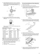
... in plastic parts bag for each burner location. 5. Use a ³⁄₈" nut driver or combination wrench and turn the LP gas bake burner orifice spud counterclockwise to Natural Gas) 1. Apply masking tape to the end of the flame spreader. Remove 2 screws at the rear of the bake burner off the oven... orifice, disconnect the igniter wire, and set it . A B XXX A. Orifice spud B. Natural Gas Orifice Spud Chart Burner Rating Color Size ID Number 17,000 BTU 15,000/15,500 BTU 14,200 BTU 13,000/13,500 BTU 12,000/12...
... in plastic parts bag for each burner location. 5. Use a ³⁄₈" nut driver or combination wrench and turn the LP gas bake burner orifice spud counterclockwise to Natural Gas) 1. Apply masking tape to the end of the flame spreader. Remove 2 screws at the rear of the bake burner off the oven... orifice, disconnect the igniter wire, and set it . A B XXX A. Orifice spud B. Natural Gas Orifice Spud Chart Burner Rating Color Size ID Number 17,000 BTU 15,000/15,500 BTU 14,200 BTU 13,000/13,500 BTU 12,000/12...


