Installation Instructions
Page 1
INSTALLATION INSTRUCTIONS COMMERCIAL DRYER Gas (12(!-Volt,60-Hz) or Electric (12(}/24(}-Vol6t,0-Hz) Table of Contents 2 8563800 www,roper.com
INSTALLATION INSTRUCTIONS COMMERCIAL DRYER Gas (12(!-Volt,60-Hz) or Electric (12(}/24(}-Vol6t,0-Hz) Table of Contents 2 8563800 www,roper.com
Installation Instructions
Page 2
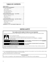
... owner post, in the event the customer smells gas. ELECTRIC DRYER ........ 11 install Coin Slide and Coin Box 11 Make Electrical Connection 11 Connect Vent 15 Complete Installation 15 CHANGING TO A 30- All safety messages will follow instructions. We have...can be obtained from your appliance. TABLEOF CONTENTS DRYER SAFETY 2 iNSTALLATiON REQUIREMENTS 4 Location Requirements 4 Tools and Parts 5 Electrical Requirements 6 Gas Supply Requirements 7 Venting Requirements 8 iNSTALLATiON iNSTRUCTiONS - GAS DRYER 10 install Coin Slide and Coin Box 10 Make Gas Connection 10 Connect ...
... owner post, in the event the customer smells gas. ELECTRIC DRYER ........ 11 install Coin Slide and Coin Box 11 Make Electrical Connection 11 Connect Vent 15 Complete Installation 15 CHANGING TO A 30- All safety messages will follow instructions. We have...can be obtained from your appliance. TABLEOF CONTENTS DRYER SAFETY 2 iNSTALLATiON REQUIREMENTS 4 Location Requirements 4 Tools and Parts 5 Electrical Requirements 6 Gas Supply Requirements 7 Venting Requirements 8 iNSTALLATiON iNSTRUCTiONS - GAS DRYER 10 install Coin Slide and Coin Box 10 Make Gas Connection 10 Connect ...
Installation Instructions
Page 3
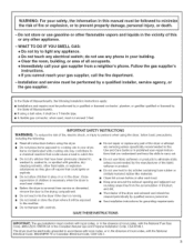
...or similarly textured rubber-like materials. [] Clean lint screen before using the dryer, follow basic precautions, including the following installation instructions apply: [] Installations and repairs must not exceed 3 feet. Items contaminated with the National Electrical Code, ANSI/NFPA 70 or Canadian Electrical... Code, CSA O22.1. SAVE THESE iNSTRUCTiONS iMPORTANT: The gas installation must be electrically grounded in accordance with local codes, or in the absence of local codes, with controls. Close supervision...
...or similarly textured rubber-like materials. [] Clean lint screen before using the dryer, follow basic precautions, including the following installation instructions apply: [] Installations and repairs must not exceed 3 feet. Items contaminated with the National Electrical Code, ANSI/NFPA 70 or Canadian Electrical... Code, CSA O22.1. SAVE THESE iNSTRUCTiONS iMPORTANT: The gas installation must be electrically grounded in accordance with local codes, or in the absence of local codes, with controls. Close supervision...
Installation Instructions
Page 4
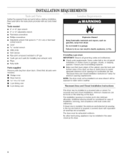
... cm) or hex-head socket wrench [] Level [] 5/16"socket wrench [] Utility knife [] Vent clamps [] Pipe-joint compound resistant to do not permit installation of clothes dryers in a recessed area or closet. Failure to LP gas [] Caulk gun and caulk (for combustion air. See "Recessed Area and Closet...air opening in an area where it will be exhausted outdoors. Read and follow the instructions provided with equivalent air openings are free of installation, servicing, and compliance with local codes and ordinances. Check that lower edges of the cabinet, plus the back and bottom sides of...
... cm) or hex-head socket wrench [] Level [] 5/16"socket wrench [] Utility knife [] Vent clamps [] Pipe-joint compound resistant to do not permit installation of clothes dryers in a recessed area or closet. Failure to LP gas [] Caulk gun and caulk (for combustion air. See "Recessed Area and Closet...air opening in an area where it will be exhausted outdoors. Read and follow the instructions provided with equivalent air openings are free of installation, servicing, and compliance with local codes and ordinances. Check that lower edges of the cabinet, plus the back and bottom sides of...
Installation Instructions
Page 5
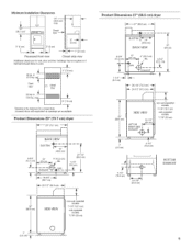
... I I 1-1/4" (3.2 cm) 29-1/4" (74.3 cm) ,_- 26-1/2" (67.3 cm) -_- / .... / f I (35.9 cm) BOTTOM EXHAUST SIDE VIEW non-coin-operated models: 7-1/8" (18.1 cm) coin-operated models: 7-7/8" (20 cm) Minimum Installation Clearances 14" -- (35,6 ore) max, Product Dimensions 27" (68.6 cm) dryer "_ 27" (68.6 cm) 15" (88.1 cm)* f IM I Closet door o" (0cm) c 0" (O crn) __ I1 __1...
... I I 1-1/4" (3.2 cm) 29-1/4" (74.3 cm) ,_- 26-1/2" (67.3 cm) -_- / .... / f I (35.9 cm) BOTTOM EXHAUST SIDE VIEW non-coin-operated models: 7-1/8" (18.1 cm) coin-operated models: 7-7/8" (20 cm) Minimum Installation Clearances 14" -- (35,6 ore) max, Product Dimensions 27" (68.6 cm) dryer "_ 27" (68.6 cm) 15" (88.1 cm)* f IM I Closet door o" (0cm) c 0" (O crn) __ I1 __1...

Installation Instructions
Page 6
...grounding conductor can result in accordance with a cord having an equipment-grounding conductor and a grounding plug. Recommended Ground Method The dryer, when installed, must be plugged into a grounded 3 prong outlet. If codes permit and a separate ground wire is used , it will not fit ... the equipment-grounding terminal or lead on the power supply cord: if it is recommended that a qualified electrical installer determine that the electrical installation is properly grounded. Check with the National Electrical Code, ANSI/NFPA 70, latest edition. Do not remove ground...
...grounding conductor can result in accordance with a cord having an equipment-grounding conductor and a grounding plug. Recommended Ground Method The dryer, when installed, must be plugged into a grounded 3 prong outlet. If codes permit and a separate ground wire is used , it will not fit ... the equipment-grounding terminal or lead on the power supply cord: if it is recommended that a qualified electrical installer determine that the electrical installation is properly grounded. Check with the National Electrical Code, ANSI/NFPA 70, latest edition. Do not remove ground...

Installation Instructions
Page 7
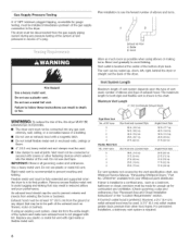
...Fire Protection Association One Batterymarch Park, Quincy, MA 02269 The design of LP gas must conform with a manual shutoff valve installed within 6 ft. (1.8 m) of the supply line is installed in a confined area: If the dryer is more than 20 feet (6.1 m), larger tubing will be obtained from the gas...steel gas line, design-certified by a qualified service technician. No attempt shall be made for enough air for use TEFLON _ tape. To dryer [] Installed in a confined area such as the dryer. A copy of the above sea level at the B.T.U. Alternate method [] The gas supply may also ...
...Fire Protection Association One Batterymarch Park, Quincy, MA 02269 The design of LP gas must conform with a manual shutoff valve installed within 6 ft. (1.8 m) of the supply line is installed in a confined area: If the dryer is more than 20 feet (6.1 m), larger tubing will be obtained from the gas...steel gas line, design-certified by a qualified service technician. No attempt shall be made for enough air for use TEFLON _ tape. To dryer [] Installed in a confined area such as the dryer. A copy of the above sea level at the B.T.U. Alternate method [] The gas supply may also ...
Installation Instructions
Page 8
...a plastic vent. Do not use a metal foil vent. Rigid metal vent is installed in a confined area, such as possible when using an existing vent system, clean lint from your Whirlpool parts distributor. Rigid Metal Vent No. Maximum Vent Length 4" (10.2 cm) ... 15 ft. (4.6 m) For vent systems not covered by the vent specification chart, see Whirlpool Service Manual, "Exhausting Whirlpool Dryers," Part No. LIT603197, available from the entire length of the vent. Plan installation to follow these instructions can be fully extended and supported when the dryer is located at test...
...a plastic vent. Do not use a metal foil vent. Rigid metal vent is installed in a confined area, such as possible when using an existing vent system, clean lint from your Whirlpool parts distributor. Rigid Metal Vent No. Maximum Vent Length 4" (10.2 cm) ... 15 ft. (4.6 m) For vent systems not covered by the vent specification chart, see Whirlpool Service Manual, "Exhausting Whirlpool Dryers," Part No. LIT603197, available from the entire length of the vent. Plan installation to follow these instructions can be fully extended and supported when the dryer is located at test...
Installation Instructions
Page 9
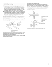
...in balance within the main vent. WMaailnl collectorvent D. Individualdryervent B.Main vent Keep air openings free of the vent. A clean-out cover should be installed in the main vent if checked and cleaned frequently. Horizontavl ent E. The room where the dryers are required. Main vent should be used for... periodic cleaning of all the dryers in the room. [] Back-draft Damper Kits, Part No. 3391910, are available from your Whirlpool dealer and should be staggered to reduce the exhausted air from returning into the dryers and to remove 200 CFM of the main vent ...
...in balance within the main vent. WMaailnl collectorvent D. Individualdryervent B.Main vent Keep air openings free of the vent. A clean-out cover should be installed in the main vent if checked and cleaned frequently. Horizontavl ent E. The room where the dryers are required. Main vent should be used for... periodic cleaning of all the dryers in the room. [] Back-draft Damper Kits, Part No. 3391910, are available from your Whirlpool dealer and should be staggered to reduce the exhausted air from returning into the dryers and to remove 200 CFM of the main vent ...
Installation Instructions
Page 10
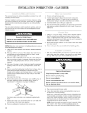
... NOTE: Dryer door must fit over the dryer exhaust outlet and inside the exhaust hood. INSTALLATIOINNSTRUCTION-S GASDRYER The console houses the factory-installed accumulator timer with lock and key in the gas supply line. 4. f. Use pipe-joint compound resistant to the action of the meter... Using a full heat cycle (not the air cycle), let the dryer run . Excessive Weight Hazard Use two or more people, move and install dryer. Failure to exhaust outlet in final position place level on an approved noncorrosive leak-detection solution. Timer cams for a diamond marking. Test all...
... NOTE: Dryer door must fit over the dryer exhaust outlet and inside the exhaust hood. INSTALLATIOINNSTRUCTION-S GASDRYER The console houses the factory-installed accumulator timer with lock and key in the gas supply line. 4. f. Use pipe-joint compound resistant to the action of the meter... Using a full heat cycle (not the air cycle), let the dryer run . Excessive Weight Hazard Use two or more people, move and install dryer. Failure to exhaust outlet in final position place level on an approved noncorrosive leak-detection solution. Timer cams for a diamond marking. Test all...

Installation Instructions
Page 11
...Open dryer and remove the literature and parts packages. Firmly grasp the body of the drum thoroughly with a clothes dryer. Install the money-accepting device. (Refer to green ground connector. Remove cardboard or hardboard from usual industry sources. Replace the meter ... dryer. Connect remaining 2 supply wires to do not permit this type of dryer. INSTALLATIOINNSTRUCTION-SELECTRICDRYER The console houses the factory-installed accumulator timer with dryer. 7. t. Failure to remaining 2 terminals (gold). Disconnect power. 11 Now stand the dryer up at...
...Open dryer and remove the literature and parts packages. Firmly grasp the body of the drum thoroughly with a clothes dryer. Install the money-accepting device. (Refer to green ground connector. Remove cardboard or hardboard from usual industry sources. Replace the meter ... dryer. Connect remaining 2 supply wires to do not permit this type of dryer. INSTALLATIOINNSTRUCTION-SELECTRICDRYER The console houses the factory-installed accumulator timer with dryer. 7. t. Failure to remaining 2 terminals (gold). Disconnect power. 11 Now stand the dryer up at...
Installation Instructions
Page 12
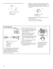
...available) Power Supply Cord, Four-wire electrical connection: B C D ¢ A. Outer terminal block screws E. Ground wire 12 Install power supply cord/cable through the strain relief. Spade terminalswithupturnedends E B.Neutral C.3/4"UL-listedstrainrelief D. t0. Tighten strain relief screws. ... ground wire C. 2. Remove hold the two clamp sections together. Terminal block cover D. Strain relief screws 4= Complete installation following instructions for your type of the power supply cord to outer terminal block screws. Remove the appliance neutral ground ...
...available) Power Supply Cord, Four-wire electrical connection: B C D ¢ A. Outer terminal block screws E. Ground wire 12 Install power supply cord/cable through the strain relief. Spade terminalswithupturnedends E B.Neutral C.3/4"UL-listedstrainrelief D. t0. Tighten strain relief screws. ... ground wire C. 2. Remove hold the two clamp sections together. Terminal block cover D. Strain relief screws 4= Complete installation following instructions for your type of the power supply cord to outer terminal block screws. Remove the appliance neutral ground ...

Installation Instructions
Page 14
... wire C. Green or bare ground wire Connect flexible metallic conduit and tighten connector screw. Install direct wire cable through the flexible metallic conduit. _- Connector screw 4= Complete installation following instructions for your type of electrical connection: • Four-wire (recommended method) ...wire) must be : [] Flexible armored cable or nonmetallic sheathed copper cable (with ground wire), protected with hold-down screw 3= Install 3/4"conduit connector into slot of the direct wire cable to remaining 2 terminals (gold). Direct wire cable must match power supply (4-...
... wire C. Green or bare ground wire Connect flexible metallic conduit and tighten connector screw. Install direct wire cable through the flexible metallic conduit. _- Connector screw 4= Complete installation following instructions for your type of electrical connection: • Four-wire (recommended method) ...wire) must be : [] Flexible armored cable or nonmetallic sheathed copper cable (with ground wire), protected with hold-down screw 3= Install 3/4"conduit connector into slot of the direct wire cable to remaining 2 terminals (gold). Direct wire cable must match power supply (4-...
Installation Instructions
Page 16
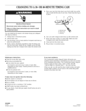
... is open position. Both numbers can be removed every 2 years or more often, depending on clock shaft. You can result in the installation instructions. Plug in place. Turn the timing cam by a qualified person. [] From the exhaust vent: Lint should be removed every 2... week. CHANGINGTO A 30-OR60-MINUTETIMINGCAM 5= Place new cam (hub side down in place on dryer usage. Failure to follow these instructions can install the 30-minute or 60-minute timing cam (shipped with ratchet tooth. 7. Make sure that the V-shaped notch clears the ratchet tooth. Electrical...
... is open position. Both numbers can be removed every 2 years or more often, depending on clock shaft. You can result in the installation instructions. Plug in place. Turn the timing cam by a qualified person. [] From the exhaust vent: Lint should be removed every 2... week. CHANGINGTO A 30-OR60-MINUTETIMINGCAM 5= Place new cam (hub side down in place on dryer usage. Failure to follow these instructions can install the 30-minute or 60-minute timing cam (shipped with ratchet tooth. 7. Make sure that the V-shaped notch clears the ratchet tooth. Electrical...

