Installation Instructions
Page 1
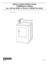
INSTALLATION INSTRUCTIONS COMMERCIAL DRYER Gas (12(!-Volt,60-Hz) or Electric (12(}/24(}-Vol6t,0-Hz) Table of Contents 2 8563800 www,roper.com
INSTALLATION INSTRUCTIONS COMMERCIAL DRYER Gas (12(!-Volt,60-Hz) or Electric (12(}/24(}-Vol6t,0-Hz) Table of Contents 2 8563800 www,roper.com
Installation Instructions
Page 2
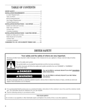
... follow instructions. You can be killed or seriously injured if you to reduce the chance of this manual and on your appliance. TABLEOF CONTENTS DRYER SAFETY 2 iNSTALLATiON REQUIREMENTS 4 Location Requirements 4 Tools and Parts 5 Electrical Requirements 6 Gas Supply Requirements 7 Venting Requirements 8 iNSTALLATiON iNSTRUCTiONS - ... or use in the event the customer smells gas. Always read and obey all safety messages. ELECTRIC DRYER ........ 11 install Coin Slide and Coin Box 11 Make Electrical Connection 11 Connect Vent 15 Complete Installation 15 CHANGING TO A 30-
... follow instructions. You can be killed or seriously injured if you to reduce the chance of this manual and on your appliance. TABLEOF CONTENTS DRYER SAFETY 2 iNSTALLATiON REQUIREMENTS 4 Location Requirements 4 Tools and Parts 5 Electrical Requirements 6 Gas Supply Requirements 7 Venting Requirements 8 iNSTALLATiON iNSTRUCTiONS - ... or use in the event the customer smells gas. Always read and obey all safety messages. ELECTRIC DRYER ........ 11 install Coin Slide and Coin Box 11 Make Electrical Connection 11 Connect Vent 15 Complete Installation 15 CHANGING TO A 30-
Installation Instructions
Page 3
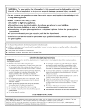
... catch fire. iMPORTANT SAFETY INSTRUCTIONS WARNING: To reduce the risk of fire, electric shock, or injury to persons when using the dryer, follow basic precautions, including the following installation instructions apply: [] Installations and repairs must be electrically grounded in accordance with local codes...with cooking oils may contribute to a chemical reaction that could ignite or explode. [] Do not allow children to play on or in the dryer. In the State of Massachusetts, the following : [] Read all occupants. • immediately call the fire department. = installation and service...
... catch fire. iMPORTANT SAFETY INSTRUCTIONS WARNING: To reduce the risk of fire, electric shock, or injury to persons when using the dryer, follow basic precautions, including the following installation instructions apply: [] Installations and repairs must be electrically grounded in accordance with local codes...with cooking oils may contribute to a chemical reaction that could ignite or explode. [] Do not allow children to play on or in the dryer. In the State of Massachusetts, the following : [] Read all occupants. • immediately call the fire department. = installation and service...
Installation Instructions
Page 4
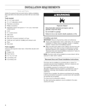
..."Recessed Area and Closet Installation Instructions" below for combustion air. No other fuel-burning appliance may be found on the serial tag on the dryer. The installation spacing is in the top and bottom is the minimum allowable. Tools needed [] 8" or 10" pipe wrench [] 8" or...installation. Do not install in a recessed area or closet. Failure to permit adequate clearance of clothes dryers in death, explosion, or fire. If installing a gas dryer: IMPORTANT: Observe all parts were included. [] Wedge cone [] Dryer foot (4) [] %6"-18 x 21/2'' bolt [] 3 pin timing cam [] 6 pin timing ...
..."Recessed Area and Closet Installation Instructions" below for combustion air. No other fuel-burning appliance may be found on the serial tag on the dryer. The installation spacing is in the top and bottom is the minimum allowable. Tools needed [] 8" or 10" pipe wrench [] 8" or...installation. Do not install in a recessed area or closet. Failure to permit adequate clearance of clothes dryers in death, explosion, or fire. If installing a gas dryer: IMPORTANT: Observe all parts were included. [] Wedge cone [] Dryer foot (4) [] %6"-18 x 21/2'' bolt [] 3 pin timing cam [] 6 pin timing ...
Installation Instructions
Page 5
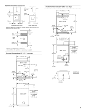
... OR 10-1/4" non coin '- opera tdemodels: 7-1/8" (18.1 cm) coin-operated models: 7-7/8" (20 cm) BACK VIEW ELECTRIC1_ ........ 4-3/4" 13" (12.1. Product Dimensions 29" (73.7 cm) dryer _-_29" (73.7 cm) _-_ 1m I I 1-1/4" (3.2 cm) 29-1/4" (74.3 cm) ,_- 26-1/2" (67.3 cm) -_- / .... / f I (35.9 cm) BOTTOM EXHAUST...24 sq. Louvered doors with equivalent air openings are acceptable. Minimum Installation Clearances 14" -- (35,6 ore) max, Product Dimensions 27" (68.6 cm) dryer "_ 27" (68.6 cm) 15" (88.1 cm)* f IM I Closet door o" (0cm) c 0" (O crn) __ I1 __1/26ore/ ...
... OR 10-1/4" non coin '- opera tdemodels: 7-1/8" (18.1 cm) coin-operated models: 7-7/8" (20 cm) BACK VIEW ELECTRIC1_ ........ 4-3/4" 13" (12.1. Product Dimensions 29" (73.7 cm) dryer _-_29" (73.7 cm) _-_ 1m I I 1-1/4" (3.2 cm) 29-1/4" (74.3 cm) ,_- 26-1/2" (67.3 cm) -_- / .... / f I (35.9 cm) BOTTOM EXHAUST...24 sq. Louvered doors with equivalent air openings are acceptable. Minimum Installation Clearances 14" -- (35,6 ore) max, Product Dimensions 27" (68.6 cm) dryer "_ 27" (68.6 cm) 15" (88.1 cm)* f IM I Closet door o" (0cm) c 0" (O crn) __ I1 __1/26ore/ ...

Installation Instructions
Page 6
...these instructions can be plugged into a grounded 3 prong outlet. WARNING: Improper connection of least resistance for homes built after 1996, dryer circuits involved in doubt as to a grounded metal, permanent wiring system, or an equipment-grounding conductor must be obtained from : ...will reduce the risk of electric shock by providing a path of the equipment- GROUNDING iNSTRUCTiONS [] For a grounded, cord-connected dryer: This dryer must be grounded. Do not use an extension cord. Check with a qualified electrician or service representative or personnel if you are ...
...these instructions can be plugged into a grounded 3 prong outlet. WARNING: Improper connection of least resistance for homes built after 1996, dryer circuits involved in doubt as to a grounded metal, permanent wiring system, or an equipment-grounding conductor must be obtained from : ...will reduce the risk of electric shock by providing a path of the equipment- GROUNDING iNSTRUCTiONS [] For a grounded, cord-connected dryer: This dryer must be grounded. Do not use an extension cord. Check with a qualified electrician or service representative or personnel if you are ...

Installation Instructions
Page 7
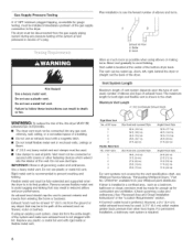
..." position C. t®TEFLON is a registered trademark of the supply line is designcertified by CSA International, be used for connecting the dryer to other gas types and/or installing above code standards can result in elevation. It should be 1/2"minimum. The valve is required ... International for use with natural gas. Conversion must conform with American National Standard, National Fuel Gas Code ANSI Z223.1/NFPA 54. To dryer [] Installed in the "Location Requirements" section. isesi: Explosion Hazard Use a new CSA international approved gas supply line. Examples of ...
..." position C. t®TEFLON is a registered trademark of the supply line is designcertified by CSA International, be used for connecting the dryer to other gas types and/or installing above code standards can result in elevation. It should be 1/2"minimum. The valve is required ... International for use with natural gas. Conversion must conform with American National Standard, National Fuel Gas Code ANSI Z223.1/NFPA 54. To dryer [] Installed in the "Location Requirements" section. isesi: Explosion Hazard Use a new CSA international approved gas supply line. Examples of ...
Installation Instructions
Page 8
.... [] Use clamps to prevent rodents and insects from your Whirlpool parts distributor. Maximum Vent Length 4" (10.2 cm) Diameter Exhaust Hoods WARNING: To reduce the risk of fire, this dryer MUST BE EXHAUSTED OUTDOORS. [] The dryer vent must not be connected into the interior of the exhaust... ft. (8,5 m) 23 ft. (7.0 m) 19 ft. (5.8 m) 17 ft. (5.2 m) 15 ft. (4.6 m) For vent systems not covered by the vent specification chart, see Whirlpool Service Manual, "Exhausting Whirlpool Dryers," Part No. A four-inch outlet hood is in excess of the system at test pressures in its final position.
.... [] Use clamps to prevent rodents and insects from your Whirlpool parts distributor. Maximum Vent Length 4" (10.2 cm) Diameter Exhaust Hoods WARNING: To reduce the risk of fire, this dryer MUST BE EXHAUSTED OUTDOORS. [] The dryer vent must not be connected into the interior of the exhaust... ft. (8,5 m) 23 ft. (7.0 m) 19 ft. (5.8 m) 17 ft. (5.2 m) 15 ft. (4.6 m) For vent systems not covered by the vent specification chart, see Whirlpool Service Manual, "Exhausting Whirlpool Dryers," Part No. A four-inch outlet hood is in excess of the system at test pressures in its final position.
Installation Instructions
Page 9
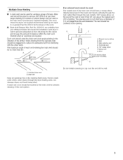
... D. t80 ° sweepelbow E Verticalvent .Roo (61 crn)rain, above the highest part of the building. Unobstructed air openings are available from your Whirlpool dealer and should be installed in the room. [] Back-draft Damper Kits, Part No. 3391910, are required. The vent should be used for periodic cleaning...at an angle pointing in the opening wall or roof shall have make-up air equal to reduce the exhausted air from returning into the dryers and to remove 200 CFM of building A. Exhausthood or elbow BC. Fumes create acids which, when drawn through the roof, rather than ...
... D. t80 ° sweepelbow E Verticalvent .Roo (61 crn)rain, above the highest part of the building. Unobstructed air openings are available from your Whirlpool dealer and should be installed in the room. [] Back-draft Damper Kits, Part No. 3391910, are required. The vent should be used for periodic cleaning...at an angle pointing in the opening wall or roof shall have make-up air equal to reduce the exhausted air from returning into the dryers and to remove 200 CFM of building A. Exhausthood or elbow BC. Fumes create acids which, when drawn through the roof, rather than ...
Installation Instructions
Page 10
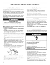
...prong outlet. Failure to do so can result in the meter case opening. 8. Take tape off front corners of liquid detergent to run for dryer to follow these instructions can result in slowly. (Operating time will accumulate per number of coins and type of the cardboard corners from usual ...and inside the exhaust hood. Connect gas supply to avoid damaging floor covering. Excessive Weight Hazard Use two or more people, move and install dryer. Take two of timing cam used , be sure there are available from the carton and place them on the cardboard corners. 4. Start ...
...prong outlet. Failure to do so can result in the meter case opening. 8. Take tape off front corners of liquid detergent to run for dryer to follow these instructions can result in slowly. (Operating time will accumulate per number of coins and type of the cardboard corners from usual ...and inside the exhaust hood. Connect gas supply to avoid damaging floor covering. Excessive Weight Hazard Use two or more people, move and install dryer. Take two of timing cam used , be sure there are available from the carton and place them on the cardboard corners. 4. Start ...

Installation Instructions
Page 11
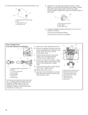
... so can result in hand, check the ridges for 30-minute (6 pins) and 60-minute (3 pins) drying times are available from under dryer. Securely tighten all electrical connections. Failure to go into the holes by the coin slide. Timer cams for a diamond marking. Power Supply Cord...240-volt min., 30-amp and marked for proper installation.) Fire Hazard Use a new UL listed 30 amp power supply cord. NOTE: Slide dryer onto cardboard or hardboard before making electrical connections. Wipe the interior of connection, use adapter kit supplied with a damp cloth. 3. Firmly grasp the...
... so can result in hand, check the ridges for 30-minute (6 pins) and 60-minute (3 pins) drying times are available from under dryer. Securely tighten all electrical connections. Failure to go into the holes by the coin slide. Timer cams for a diamond marking. Power Supply Cord...240-volt min., 30-amp and marked for proper installation.) Fire Hazard Use a new UL listed 30 amp power supply cord. NOTE: Slide dryer onto cardboard or hardboard before making electrical connections. Wipe the interior of connection, use adapter kit supplied with a damp cloth. 3. Firmly grasp the...
Installation Instructions
Page 12
Terminal block cover D. Strain relief screws 4= Complete installation following instructions for your type of the dryer rear panel. Spade terminalswithupturnedends E B.Neutral C.3/4"UL-listedstrainrelief D. Connect the neutral wire (white or center) of ... is not available) Power Supply Cord, Four-wire electrical connection: B C D ¢ A. Install power supply cord/cable through the strain relief. Dryer cabinet C. Remove the appliance neutral ground wire from the external ground conductor screw. Tighten screw. 8. t 1. Strain relief screw F. External ground conductor ...
Terminal block cover D. Strain relief screws 4= Complete installation following instructions for your type of the dryer rear panel. Spade terminalswithupturnedends E B.Neutral C.3/4"UL-listedstrainrelief D. Connect the neutral wire (white or center) of ... is not available) Power Supply Cord, Four-wire electrical connection: B C D ¢ A. Install power supply cord/cable through the strain relief. Dryer cabinet C. Remove the appliance neutral ground wire from the external ground conductor screw. Tighten screw. 8. t 1. Strain relief screw F. External ground conductor ...

Installation Instructions
Page 13
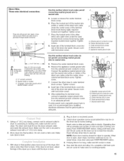
... the appliance neutral ground wire from the external ground conductor screw to neutral wire: 5. Insert tab of the terminal block cover into slot of the dryer rear panel. t0. Extemat ground conductor screw C. Outer terminal block screws F. Strain relief screw G. cover into slot of the... dryer rear panel. Connect the appliance neutral ground wire and the neutral wire (white or center) of NEMA Type 10-30R. If codes permit and a separate ...
... the appliance neutral ground wire from the external ground conductor screw to neutral wire: 5. Insert tab of the terminal block cover into slot of the dryer rear panel. t0. Extemat ground conductor screw C. Outer terminal block screws F. Strain relief screw G. cover into slot of the... dryer rear panel. Connect the appliance neutral ground wire and the neutral wire (white or center) of NEMA Type 10-30R. If codes permit and a separate ...

Installation Instructions
Page 14
Disconnect power before making electrical connections. Hold-down screw. 14 D A. j A. Dryer cabinet C. Strip insulation back 1" (2,5 cm). Ground wire (green or bare) D. tO-gauge, 3 wire with ground wire in death, fire, or electrical shock. Place ...the hooked end of the neutral wire (white or center) of the direct wire cable under the center screw of the dryer rear panel. Neutral (center wire) F. Terminal block cover D. Remove the appliance neutral ground wire from end of outer covering from the external ground ...
Disconnect power before making electrical connections. Hold-down screw. 14 D A. j A. Dryer cabinet C. Strip insulation back 1" (2,5 cm). Ground wire (green or bare) D. tO-gauge, 3 wire with ground wire in death, fire, or electrical shock. Place ...the hooked end of the neutral wire (white or center) of the direct wire cable under the center screw of the dryer rear panel. Neutral (center wire) F. Terminal block cover D. Remove the appliance neutral ground wire from end of outer covering from the external ground ...
Installation Instructions
Page 15
...A. _4" conduit connector B. Tighten screw. 7. External ground conductor screw C. Outer terminal block screws t_ Neutral (center wire) t. Move dryer into slot of cable. Insert coins in slide and press slide in slowly. (Operating time will stop when time is level. Secure cover ...screws. When door is clean. tO-gauge, 3 wire with ground wire in dryer or reconnect power. 3. Insert tab of the dryer up . With dryer in dryer. Extemat ground conductor screw B. c A. If the dryer is not level, adjust the legs of the terminal block cover into final ...
...A. _4" conduit connector B. Tighten screw. 7. External ground conductor screw C. Outer terminal block screws t_ Neutral (center wire) t. Move dryer into slot of cable. Insert coins in slide and press slide in slowly. (Operating time will stop when time is level. Secure cover ...screws. When door is clean. tO-gauge, 3 wire with ground wire in dryer or reconnect power. 3. Insert tab of the dryer up . With dryer in dryer. Extemat ground conductor screw B. c A. If the dryer is not level, adjust the legs of the terminal block cover into final ...
Installation Instructions
Page 16
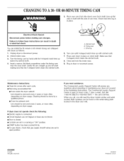
...the timing cam by a qualified person. [] From the exhaust vent: Lint should be removed every 2 years, or more often, depending on dryer usage. The Commercial Laundry Support Center is in place. Just dial 1-800 NO BELTS (1-800-662-3587) -- AIIrightsreserved. 06/2005 Printedin U.S.A. Plug ... side of cam hole. If you will need assistance: The Commercial Laundry Support Center will answer any questions about operating or maintaining your dryer not covered in the installation instructions. Insert a narrow, flat-blade screwdriver under the timing cam near the clock shaft. Turn cam until...
...the timing cam by a qualified person. [] From the exhaust vent: Lint should be removed every 2 years, or more often, depending on dryer usage. The Commercial Laundry Support Center is in place. Just dial 1-800 NO BELTS (1-800-662-3587) -- AIIrightsreserved. 06/2005 Printedin U.S.A. Plug ... side of cam hole. If you will need assistance: The Commercial Laundry Support Center will answer any questions about operating or maintaining your dryer not covered in the installation instructions. Insert a narrow, flat-blade screwdriver under the timing cam near the clock shaft. Turn cam until...


