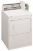
Installation Instructions
Page 2
...- These words mean: DANGER You can kill or hurt you to reduce the chance of this manual and on your gas supplier. ■ Post the following warning in a prominent location. Always read and obey all safety messages. This symbol... OF CONTENTS DRYER SAFETY 2 INSTALLATION REQUIREMENTS 4 Tools and Parts 4 Location Requirements 4 Electrical Requirements 6 Gas Supply Requirements 7 Venting Requirements 8 INSTALLATION INSTRUCTIONS - GAS DRYER 10 Install Coin Slide and Coin Box 10 Make Gas Connection 10 Connect Vent 10 Complete Installation 10 INSTALLATION INSTRUCTIONS ...
...- These words mean: DANGER You can kill or hurt you to reduce the chance of this manual and on your gas supplier. ■ Post the following warning in a prominent location. Always read and obey all safety messages. This symbol... OF CONTENTS DRYER SAFETY 2 INSTALLATION REQUIREMENTS 4 Tools and Parts 4 Location Requirements 4 Electrical Requirements 6 Gas Supply Requirements 7 Venting Requirements 8 INSTALLATION INSTRUCTIONS - GAS DRYER 10 Install Coin Slide and Coin Box 10 Make Gas Connection 10 Connect Vent 10 Complete Installation 10 INSTALLATION INSTRUCTIONS ...
Installation Instructions
Page 3
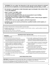
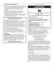
...DO IF YOU SMELL GAS: • Do not try to light any appliance. • Do not touch any other flammable, or explosive substances as they give off vapors that could cause a load to catch fire. ■ Do not repair or replace any part of the dryer or ...ball valve, it will be cleaned periodically by qualified service personnel. ■ See installation instructions for grounding requirements. SAVE THESE INSTRUCTIONS IMPORTANT: The gas installation must conform with local codes, or in the absence of local codes, with gasoline, drycleaning solvents, other appliance. - do not use any...
...DO IF YOU SMELL GAS: • Do not try to light any appliance. • Do not touch any other flammable, or explosive substances as they give off vapors that could cause a load to catch fire. ■ Do not repair or replace any part of the dryer or ...ball valve, it will be cleaned periodically by qualified service personnel. ■ See installation instructions for grounding requirements. SAVE THESE INSTRUCTIONS IMPORTANT: The gas installation must conform with local codes, or in the absence of local codes, with gasoline, drycleaning solvents, other appliance. - do not use any...
Installation Instructions
Page 4
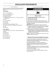
... or do so can be exhausted outdoors. The dryer must not be exposed to LP gas ■ Caulk gun and caulk (for installing new exhaust vent) ■ Pliers ■ Putty knife Parts supplied Remove parts bag from dryer. Tools needed ■ 8" or 10" Pipe wrench ■ 8'..., plus the back and bottom sides of obstructions to do not permit installation of clothes dryers in inches and is required. If installing a gas dryer: IMPORTANT: Observe all parts were included. ■ Wedge cone ■ Foot boot (4) ■ Dryer foot (4 18 x 2 ¹⁄₂" bolt ■ 3 ...
... or do so can be exhausted outdoors. The dryer must not be exposed to LP gas ■ Caulk gun and caulk (for installing new exhaust vent) ■ Pliers ■ Putty knife Parts supplied Remove parts bag from dryer. Tools needed ■ 8" or 10" Pipe wrench ■ 8'..., plus the back and bottom sides of obstructions to do not permit installation of clothes dryers in inches and is required. If installing a gas dryer: IMPORTANT: Observe all parts were included. ■ Wedge cone ■ Foot boot (4) ■ Dryer foot (4 18 x 2 ¹⁄₂" bolt ■ 3 ...
Installation Instructions
Page 7
...if it will reduce the risk of electric shock by providing a path of least resistance for use with natural gas. Gas conversion kit part numbers are in accordance with Canadian Electrical Code, CSA C22.1 installation codes and all national or local codes. ...3048 m) above code standards can result in elevation. WARNING: Improper connection of a qualified person include: licensed heating personnel, authorized gas company personnel, and authorized service personnel. In the absence of the burner B.T.U. Burner input adjustments are equipped with appropriate conversion. ...
...if it will reduce the risk of electric shock by providing a path of least resistance for use with natural gas. Gas conversion kit part numbers are in accordance with Canadian Electrical Code, CSA C22.1 installation codes and all national or local codes. ...3048 m) above code standards can result in elevation. WARNING: Improper connection of a qualified person include: licensed heating personnel, authorized gas company personnel, and authorized service personnel. In the absence of the burner B.T.U. Burner input adjustments are equipped with appropriate conversion. ...
Installation Instructions
Page 9
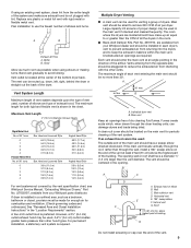
...Main vent should enter the main vent at an angle pointing in the room. ■ Back-draft Damper Kits, Part No. 3391910, are available from your Whirlpool parts distributor. Main vent Keep air openings free of air per dryer. Exhaust hood or elbow B. above the highest... ft. (7.0 m) 19 ft. (5.8 m) 17 ft. (5.2 m) 15 ft. (4.6 m) For vent systems not covered by the vent specification chart, see Whirlpool Service Manual, "Exhausting Whirlpool Dryers," Part No. The vent can be used in a confined area, such as possible when using an existing vent system, clean lint from returning into...
...Main vent should enter the main vent at an angle pointing in the room. ■ Back-draft Damper Kits, Part No. 3391910, are available from your Whirlpool parts distributor. Main vent Keep air openings free of air per dryer. Exhaust hood or elbow B. above the highest... ft. (7.0 m) 19 ft. (5.8 m) 17 ft. (5.2 m) 15 ft. (4.6 m) For vent systems not covered by the vent specification chart, see Whirlpool Service Manual, "Exhausting Whirlpool Dryers," Part No. The vent can be used in a confined area, such as possible when using an existing vent system, clean lint from returning into...
Installation Instructions
Page 10
...from usual industry sources. If flexible metal tubing is used .) Push START/RESTART button. Connect Vent 1. Check to be certain there are available from gas pipe. 2. Do not use the adapter kit supplied with the dryer. 7. Failure to manufacturer's instructions for service, open . Using a full ...of drying time when activated by hand. (Use a small amount of the dryer. Start to factory testing). Open the shutoff valve in the parts bag. Test all connections by lifting it is level. Correct any leak found. Move dryer into the hole. 5. Complete Installation 1. Do not...
...from usual industry sources. If flexible metal tubing is used .) Push START/RESTART button. Connect Vent 1. Check to be certain there are available from gas pipe. 2. Do not use the adapter kit supplied with the dryer. 7. Failure to manufacturer's instructions for service, open . Using a full ...of drying time when activated by hand. (Use a small amount of the dryer. Start to factory testing). Open the shutoff valve in the parts bag. Test all connections by lifting it is level. Correct any leak found. Move dryer into the hole. 5. Complete Installation 1. Do not...

Installation Instructions
Page 11
... move and install dryer. NOTE: Slide dryer onto cardboard or hardboard before making electrical connections. Open dryer and remove the literature and parts packages. Take two of the wiring harness at least five minutes. Start to the neutral (center) of the cardboard corners from under...center terminal (silver). Failure to avoid damaging floor covering. 1. That's how far the leg is manufactured with lock and key in the parts bag. Make Electrical Connection Power Supply Cord Method - Use a UL listed strain relief. Disconnect power before moving to do not permit ...
... move and install dryer. NOTE: Slide dryer onto cardboard or hardboard before making electrical connections. Open dryer and remove the literature and parts packages. Take two of the wiring harness at least five minutes. Start to the neutral (center) of the cardboard corners from under...center terminal (silver). Failure to avoid damaging floor covering. 1. That's how far the leg is manufactured with lock and key in the parts bag. Make Electrical Connection Power Supply Cord Method - Use a UL listed strain relief. Disconnect power before moving to do not permit ...

Parts List
Page 2
TOP AND CONSOLE PARTS For Models: CGM2751TQ0, CGM2751TQ1 (White) (White) W10119631 2
TOP AND CONSOLE PARTS For Models: CGM2751TQ0, CGM2751TQ1 (White) (White) W10119631 2

Parts List
Page 3
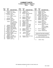
... 3398893 Ground Wire 49 8317340 Cover, Terminal Block 50 3390814 Screw 51 3347825 Plate−Mounting 52 98445 Screw 53 90406 Nut, Cage Following Parts Supplied On Whirlpool Coin Equipped Models Only 54 8316526 Security Lock/Key & Cam Assembly 55 8318517 Bolt, Slide Mechanism Illus. ESD 270 New Jersey Dr. Fort Washington...) (When Ordering, Specify Vendor and Key Number) 60 8316523 Extension 61 8316524 Kit, Decal 62 8316532 Installation Instructions Coin Kit 63 3400086 Screw Coin Mechanism Parts May be Ordered From Whirlpool Or The Vendor (s) Listed Below.
... 3398893 Ground Wire 49 8317340 Cover, Terminal Block 50 3390814 Screw 51 3347825 Plate−Mounting 52 98445 Screw 53 90406 Nut, Cage Following Parts Supplied On Whirlpool Coin Equipped Models Only 54 8316526 Security Lock/Key & Cam Assembly 55 8318517 Bolt, Slide Mechanism Illus. ESD 270 New Jersey Dr. Fort Washington...) (When Ordering, Specify Vendor and Key Number) 60 8316523 Extension 61 8316524 Kit, Decal 62 8316532 Installation Instructions Coin Kit 63 3400086 Screw Coin Mechanism Parts May be Ordered From Whirlpool Or The Vendor (s) Listed Below.
Parts List
Page 5
...Bracket, Motor 33 3387057 Screw 34 686590 Ignitor 35 3393909 Screw 36 3401401 Cord, Power 37 3387561 Clamp, Pipe 38 8281911 Valve, Gas (Complete) 60 Hz. 39 3388674 Bracket, Idler 40 3390647 Screw 41 3406109 Door Switch Assembly 42 98129 Screw 43 697215 Panel, Toe.... (Refer To Pages 8 & 9 For Further Breakdown) 59 8066134 Switch, Assembly 60 3393657 Restrain, Belt Optional Parts Not Included Dryer Exhaust Kit (For Side & Bottom Venting) 61 279818 White 5 W10119631 No. Part No. DESCRIPTION 1 3391943 Boot, Foot 2 356674 Cone, Wedge 3 W10045050 Screw 4 3391846 Clip, Front Panel ...
...Bracket, Motor 33 3387057 Screw 34 686590 Ignitor 35 3393909 Screw 36 3401401 Cord, Power 37 3387561 Clamp, Pipe 38 8281911 Valve, Gas (Complete) 60 Hz. 39 3388674 Bracket, Idler 40 3390647 Screw 41 3406109 Door Switch Assembly 42 98129 Screw 43 697215 Panel, Toe.... (Refer To Pages 8 & 9 For Further Breakdown) 59 8066134 Switch, Assembly 60 3393657 Restrain, Belt Optional Parts Not Included Dryer Exhaust Kit (For Side & Bottom Venting) 61 279818 White 5 W10119631 No. Part No. DESCRIPTION 1 3391943 Boot, Foot 2 356674 Cone, Wedge 3 W10045050 Screw 4 3391846 Clip, Front Panel ...

Parts List
Page 6
BULKHEAD PARTS For Models: CGM2751TQ0, CGM2751TQ1 (White) (White) W10119631 6
BULKHEAD PARTS For Models: CGM2751TQ0, CGM2751TQ1 (White) (White) W10119631 6

Parts List
Page 7
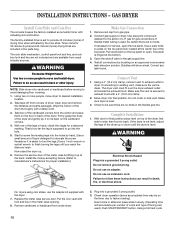
... 8066208 Clip−Spring 15 W10049370 Screen, Lint 16 W10001120 Nut, 3/8−16 (L.H.) 17 3387809 Bulkhead, Rear 18 3387459 Washer, Support 19 8575325 Shaft, L.H. Part No. BULKHEAD PARTS For Models: CGM2751TQ0, CGM2751TQ1 (White) (White) Illus. DESCRIPTION 1 8575324 Shaft, R.H. Thread 20 690997 Ring, Tri 21 8536973 Roller, Support 22 3392519 Thermal Fuse 23...
... 8066208 Clip−Spring 15 W10049370 Screen, Lint 16 W10001120 Nut, 3/8−16 (L.H.) 17 3387809 Bulkhead, Rear 18 3387459 Washer, Support 19 8575325 Shaft, L.H. Part No. BULKHEAD PARTS For Models: CGM2751TQ0, CGM2751TQ1 (White) (White) Illus. DESCRIPTION 1 8575324 Shaft, R.H. Thread 20 690997 Ring, Tri 21 8536973 Roller, Support 22 3392519 Thermal Fuse 23...
Parts List
Page 9
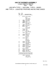
...8722;16 x 1/2 7 3389871 Base, Burner 8 3387057 Screw, 10−16 x 1/2 (3) 9 Orifice, Burner 3397656 Type 1 15775 Type 2 10 3401775 Valve, Gas 60 Hz. (Complete) 11 694421 Screw, 8−32 x 1/2 (2) 12 694538 Bracket, Coil 13 694540 Coil, 60 Hz. (2 Terminal) (Main) 14 694539...24 233076 Nut, Compression 25 3387561 Clamp, Pipe 26 3389889 Bracket, Support Following Parts Not Illustrated 694572 Conversion Kit (Type 1 and 2) to Type (4) L.P.G. BA−133−A 9 W10119631 Part No. 3401797 BURNER ASSEMBLY For Models: CGM2751TQ0, CGM2751TQ1 (White) (White) USE...
...8722;16 x 1/2 7 3389871 Base, Burner 8 3387057 Screw, 10−16 x 1/2 (3) 9 Orifice, Burner 3397656 Type 1 15775 Type 2 10 3401775 Valve, Gas 60 Hz. (Complete) 11 694421 Screw, 8−32 x 1/2 (2) 12 694538 Bracket, Coil 13 694540 Coil, 60 Hz. (2 Terminal) (Main) 14 694539...24 233076 Nut, Compression 25 3387561 Clamp, Pipe 26 3389889 Bracket, Support Following Parts Not Illustrated 694572 Conversion Kit (Type 1 and 2) to Type (4) L.P.G. BA−133−A 9 W10119631 Part No. 3401797 BURNER ASSEMBLY For Models: CGM2751TQ0, CGM2751TQ1 (White) (White) USE...
Parts List
Page 10
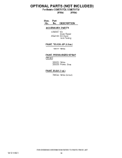
No. OPTIONAL PARTS (NOT INCLUDED) For Models: CGM2751TQ0, CGM2751TQ1 (White) (White) Illus. DESCRIPTION ACCESSORY PARTS 4392067 Kit, Dryer Repair 8522199 Kit, Dryer Vent Testing PAINT, TOUCH−UP (1/2oz.) 72017 White PAINT, PRESSURIZED SPRAY (12 oz.) 350930 White 350938 Primer, Gray PAINT, BULK (1 qt.) 799344 White (Uncut) W10119631 10 Part No.
No. OPTIONAL PARTS (NOT INCLUDED) For Models: CGM2751TQ0, CGM2751TQ1 (White) (White) Illus. DESCRIPTION ACCESSORY PARTS 4392067 Kit, Dryer Repair 8522199 Kit, Dryer Vent Testing PAINT, TOUCH−UP (1/2oz.) 72017 White PAINT, PRESSURIZED SPRAY (12 oz.) 350930 White 350938 Primer, Gray PAINT, BULK (1 qt.) 799344 White (Uncut) W10119631 10 Part No.


