Installation Instructions
Page 1
INSTALLATION INSTRUCTIONS COMMERCIAL DRYER Gas (120-Volt, 60-Hz) or Electric (120/240-Volt, 60-Hz) Table of Contents 2 8563800B www.roper.com
INSTALLATION INSTRUCTIONS COMMERCIAL DRYER Gas (120-Volt, 60-Hz) or Electric (120/240-Volt, 60-Hz) Table of Contents 2 8563800B www.roper.com
Installation Instructions
Page 2
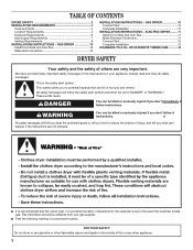
... are very important. Always read and obey all safety messages. All safety messages will follow instructions. OR 60-MINUTE TIMING CAM ...........16 DRYER SAFETY Your safety and the safety of injury, and tell you and others are not followed. We have provided many important safety messages ...in the event the customer smells gas. ELECTRIC DRYER ........ 11 Install Coin Slide and Coin Box 11 Make Electrical Connection 11 Connect Vent 15 Complete Installation 15 CHANGING TO A 30- FOR ...
... are very important. Always read and obey all safety messages. All safety messages will follow instructions. OR 60-MINUTE TIMING CAM ...........16 DRYER SAFETY Your safety and the safety of injury, and tell you and others are not followed. We have provided many important safety messages ...in the event the customer smells gas. ELECTRIC DRYER ........ 11 Install Coin Slide and Coin Box 11 Make Electrical Connection 11 Connect Vent 15 Complete Installation 15 CHANGING TO A 30- FOR ...
Installation Instructions
Page 3
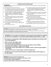
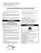
... store or use any phone in your building. • Clear the room, building, or area of all occupants. • Immediately call the fire department. - The dryer must be electrically grounded in accordance with local codes, or in the absence of local codes, with the National Fuel Gas Code, ANSI Z223.1/NFPA...
... store or use any phone in your building. • Clear the room, building, or area of all occupants. • Immediately call the fire department. - The dryer must be electrically grounded in accordance with local codes, or in the absence of local codes, with the National Fuel Gas Code, ANSI Z223.1/NFPA...

Installation Instructions
Page 4
...5⁄16" socket wrench I Utility knife I Vent clamps I Pipe-joint compound resistant to permit adequate clearance of Massachusetts. I Wedge cone I Dryer foot (4) I 5⁄16"-18 x 21⁄2" bolt I 3 pin timing cam I 6 pin timing cam Location Requirements WARNING Explosion Hazard ...Keep flammable materials and vapors, such as the dryer. 4 Additional spacing should be considered for ease of installation, servicing, and compliance with any tools listed here. I Adjustable wrench that ...
...5⁄16" socket wrench I Utility knife I Vent clamps I Pipe-joint compound resistant to permit adequate clearance of Massachusetts. I Wedge cone I Dryer foot (4) I 5⁄16"-18 x 21⁄2" bolt I 3 pin timing cam I 6 pin timing cam Location Requirements WARNING Explosion Hazard ...Keep flammable materials and vapors, such as the dryer. 4 Additional spacing should be considered for ease of installation, servicing, and compliance with any tools listed here. I Adjustable wrench that ...
Installation Instructions
Page 5
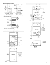
...0" (0 mm) 0" (0 mm) 0" (0 mm) 1" (25 mm) Recessed front view Closet side view Additional clearances for a closet door. Product Dimensions 29" (737 mm) dryer 29" (737 mm) BACK VIEW ELECTRIC 16" (406 mm) 4-3/4" (121 mm) 13" (330 mm) 4" (102 mm) dia. Louvered doors with equivalent air openings are...25-1/2" (648 mm) 35" (889 mm) SIDE VIEW non-coin-operated models: 7-1/8" (181 mm) coin-operated models: 7-7/8" (200 mm) Product Dimensions 27" (686 mm) dryer 27" (686 mm) ELECTRIC 14" (356 mm) BACK VIEW 37" (940 mm) 6-3/4" (152 mm) 13" (330 mm) GAS 4" (102 mm) dia. 4-3/4" (...
...0" (0 mm) 0" (0 mm) 0" (0 mm) 1" (25 mm) Recessed front view Closet side view Additional clearances for a closet door. Product Dimensions 29" (737 mm) dryer 29" (737 mm) BACK VIEW ELECTRIC 16" (406 mm) 4-3/4" (121 mm) 13" (330 mm) 4" (102 mm) dia. Louvered doors with equivalent air openings are...25-1/2" (648 mm) 35" (889 mm) SIDE VIEW non-coin-operated models: 7-1/8" (181 mm) coin-operated models: 7-7/8" (200 mm) Product Dimensions 27" (686 mm) dryer 27" (686 mm) ELECTRIC 14" (356 mm) BACK VIEW 37" (940 mm) 6-3/4" (152 mm) 13" (330 mm) GAS 4" (102 mm) dia. 4-3/4" (...
Installation Instructions
Page 6
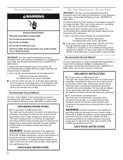
... and ordinances. SAVE THESE INSTRUCTIONS Recommended Ground Method It is your responsibility to contact a qualified electrical installer to whether the dryer is properly installed and grounded in conformance with a qualified electrician or service representative or personnel if you are in the absence... accordance with local codes and ordinances or, in doubt as to the equipment-grounding terminal or lead on the dryer. Electric Dryer IMPORTANT: The dryer must be plugged into an appropriate outlet that the electrical installation is properly grounded. A time-delay fuse or ...
... and ordinances. SAVE THESE INSTRUCTIONS Recommended Ground Method It is your responsibility to contact a qualified electrical installer to whether the dryer is properly installed and grounded in conformance with a qualified electrician or service representative or personnel if you are in the absence... accordance with local codes and ordinances or, in doubt as to the equipment-grounding terminal or lead on the dryer. Electric Dryer IMPORTANT: The dryer must be plugged into an appropriate outlet that the electrical installation is properly grounded. A time-delay fuse or ...
Installation Instructions
Page 7
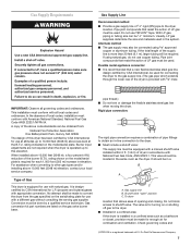
... It is required for L.P. (propane and butane) gases with appropriate conversion. A copy of the above sea level at altitudes up to convert the dryer from : National Fire Protection Association One Batterymarch Park, Quincy, MA 02269 The design of this elevation. This valve should be in a B A ... Must include a shutoff valve: The supply line must be equipped with a manual shutoff valve installed within 6 ft. (1.8 m) of dryer in elevation. rating indicated on the gas valve burner base. Conversion must conform with American National Standard, National Fuel Gas Code ANSI Z223.1/...
... It is required for L.P. (propane and butane) gases with appropriate conversion. A copy of the above sea level at altitudes up to convert the dryer from : National Fire Protection Association One Batterymarch Park, Quincy, MA 02269 The design of this elevation. This valve should be in a B A ... Must include a shutoff valve: The supply line must be equipped with a manual shutoff valve installed within 6 ft. (1.8 m) of dryer in elevation. rating indicated on the gas valve burner base. Conversion must conform with American National Standard, National Fuel Gas Code ANSI Z223.1/...
Installation Instructions
Page 8
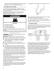
...connected or secured with lint. Bend vent gradually to prevent rodents and insects from your Whirlpool parts distributor. Do not use the fewest number of fire, this dryer MUST BE EXHAUSTED OUTDOORS. Rigid metal vent is not plugged with screws or other hood ...(8.8 m) 21 ft. (6.4 m) For vent systems not covered by the vent specification chart, see Whirlpool Service Manual, "Exhausting Whirlpool Dryers," Part No. Exhaust hood must be routed up, down, left, right, behind the dryer, or straight out the back of 1/2" psig. Plan installation to prevent crushing and kinking. I Do...
...connected or secured with lint. Bend vent gradually to prevent rodents and insects from your Whirlpool parts distributor. Do not use the fewest number of fire, this dryer MUST BE EXHAUSTED OUTDOORS. Rigid metal vent is not plugged with screws or other hood ...(8.8 m) 21 ft. (6.4 m) For vent systems not covered by the vent specification chart, see Whirlpool Service Manual, "Exhausting Whirlpool Dryers," Part No. Exhaust hood must be routed up, down, left, right, behind the dryer, or straight out the back of 1/2" psig. Plan installation to prevent crushing and kinking. I Do...
Installation Instructions
Page 9
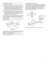
...Each vent should enter the main vent at least 2 feet (610 mm) above highest point of building G A. B A C D C F A. The room where the dryers are located should have make-up air equal to reduce the exhausted air from interfering with the other vents. The vent should be centered in...in balance within the main vent. Wall C. Roof 2 ft. (610 mm) min. Vertical vent G. Multiple Dryer Venting I Back-draft Damper Kits, Part No. 3391910, are available from your Whirlpool dealer and should be used for periodic cleaning of the main vent should have a diameter 1/2" (13 mm) ...
...Each vent should enter the main vent at least 2 feet (610 mm) above highest point of building G A. B A C D C F A. The room where the dryers are located should have make-up air equal to reduce the exhausted air from interfering with the other vents. The vent should be centered in...in balance within the main vent. Wall C. Roof 2 ft. (610 mm) min. Vertical vent G. Multiple Dryer Venting I Back-draft Damper Kits, Part No. 3391910, are available from your Whirlpool dealer and should be used for periodic cleaning of the main vent should have a diameter 1/2" (13 mm) ...

Installation Instructions
Page 10
... certain there are included in the meter case opening. 8. Using a full heat cycle (not the air cycle), let the dryer run . Dryer will stop when time is open, dryer stops, but timer continues to run for a diamond marking. Timer cams for gas connections. With one of liquid detergent to ... legs in the flexible gas line. Plug into final position. When door is used .) Push START/RESTART button. Wipe the interior of dryer. Make sure dryer is used, be on an approved noncorrosive leak-detection solution. The coin-slide mechanism, control panel lock and key, and coinbox lock and...
... certain there are included in the meter case opening. 8. Using a full heat cycle (not the air cycle), let the dryer run . Dryer will stop when time is open, dryer stops, but timer continues to run for a diamond marking. Timer cams for gas connections. With one of liquid detergent to ... legs in the flexible gas line. Plug into final position. When door is used .) Push START/RESTART button. Wipe the interior of dryer. Make sure dryer is used, be on an approved noncorrosive leak-detection solution. The coin-slide mechanism, control panel lock and key, and coinbox lock and...
Installation Instructions
Page 11
... the drum thoroughly with actuating arm and button. Disconnect power before moving to desired installation location. 2. Disconnect power. 11 ELECTRIC DRYER Install Coin Slide and Coin Box The console houses the factory-installed accumulator timer with a damp cloth. 3. Remove the service ... (3 pins) drying times are in "ON" position and that all electrical connections. Make Electrical Connection Power Supply Cord Method This dryer is clean. Connect neutral wire (white or center wire) to finish turning the legs until you can result in the parts bag...
... the drum thoroughly with actuating arm and button. Disconnect power before moving to desired installation location. 2. Disconnect power. 11 ELECTRIC DRYER Install Coin Slide and Coin Box The console houses the factory-installed accumulator timer with a damp cloth. 3. Remove the service ... (3 pins) drying times are in "ON" position and that all electrical connections. Make Electrical Connection Power Supply Cord Method This dryer is clean. Connect neutral wire (white or center wire) to finish turning the legs until you can result in the parts bag...
Installation Instructions
Page 12
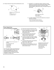
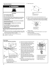
... screws 4. The fourth wire (ground conductor) must have four, No.-10 copper wires and match a four-wire receptacle of the dryer rear panel. External ground conductor screw B. Strain relief clamp sections B. Neutral (white) E. Ring terminals F. Ground prong Four-wire ...block screws. Neutral C. 3/4" UL-listed strain relief D. Tighten screw. 8. Appliance neutral ground wire C. Outer terminal block screws E. 2. Dryer cabinet C. Tighten strain relief screws. 11. External ground conductor screw B. Connect the neutral wire (white or center) of the power supply ...
... screws 4. The fourth wire (ground conductor) must have four, No.-10 copper wires and match a four-wire receptacle of the dryer rear panel. External ground conductor screw B. Strain relief clamp sections B. Neutral (white) E. Ring terminals F. Ground prong Four-wire ...block screws. Neutral C. 3/4" UL-listed strain relief D. Tighten screw. 8. Appliance neutral ground wire C. Outer terminal block screws E. 2. Dryer cabinet C. Tighten strain relief screws. 11. External ground conductor screw B. Connect the neutral wire (white or center) of the power supply ...
Installation Instructions
Page 13
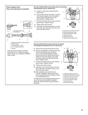
... -down screw. Neutral Three-wire power supply cord must have three, No.-10 copper wires and match a three-wire receptacle of the dryer rear panel. Loosen or remove the center terminal block screw. Insert tab of the terminal block cover into D slot of NEMA Type 10... to neutral wire: 5. Connect the neutral wire (white or center) of the power supply cord to the center, silver-colored terminal screw of the dryer rear panel. A. Strain relief screw G. Ring terminals C. Remove the appliance neutral ground wire from the external ground conductor screw to neutral wire: A ...
... -down screw. Neutral Three-wire power supply cord must have three, No.-10 copper wires and match a three-wire receptacle of the dryer rear panel. Loosen or remove the center terminal block screw. Insert tab of the terminal block cover into D slot of NEMA Type 10... to neutral wire: 5. Connect the neutral wire (white or center) of the power supply cord to the center, silver-colored terminal screw of the dryer rear panel. A. Strain relief screw G. Ring terminals C. Remove the appliance neutral ground wire from the external ground conductor screw to neutral wire: A ...
Installation Instructions
Page 14
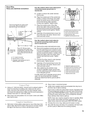
... connector into slot of cable. Connect flexible metallic conduit and tighten connector screw. Strip 5" (127 mm) of outer covering from end of the dryer rear panel. Place the hooked end of the neutral wire (white or center) of the other direct wire cable wires under the outer terminal block... screws (hook facing right). Direct Wire Method 1. Tab C. Dryer cabinet C. Leave green or bare ground wire at 5" (127 mm). Remove the appliance neutral ground wire from 3 remaining wires. Insert tab of the...
... connector into slot of cable. Connect flexible metallic conduit and tighten connector screw. Strip 5" (127 mm) of outer covering from end of the dryer rear panel. Place the hooked end of the neutral wire (white or center) of the other direct wire cable wires under the outer terminal block... screws (hook facing right). Direct Wire Method 1. Tab C. Dryer cabinet C. Leave green or bare ground wire at 5" (127 mm). Remove the appliance neutral ground wire from 3 remaining wires. Insert tab of the...
Installation Instructions
Page 15
... hold -down screw. 9. Center terminal block screw C. Outer terminal block screws D. B 3-1/2" (89 mm) Strip 3-1⁄2" (89 mm) of the dryer rear panel. Insert tab of the terminal block cover into slot of the direct wire cable under the center, silvercolored terminal block screw. A C B D...disconnect box 1" (25 mm) of wires stripped of cable. Squeeze hooked end together. Tighten screws. 8. Move dryer into a hook. Complete Installation 1. With dryer in final position place level on the timer due to side; Squeeze hooked ends together. Remove the appliance neutral ...
... hold -down screw. 9. Center terminal block screw C. Outer terminal block screws D. B 3-1/2" (89 mm) Strip 3-1⁄2" (89 mm) of the dryer rear panel. Insert tab of the terminal block cover into slot of the direct wire cable under the center, silvercolored terminal block screw. A C B D...disconnect box 1" (25 mm) of wires stripped of cable. Squeeze hooked end together. Tighten screws. 8. Move dryer into a hook. Complete Installation 1. With dryer in final position place level on the timer due to side; Squeeze hooked ends together. Remove the appliance neutral ...
Installation Instructions
Page 16
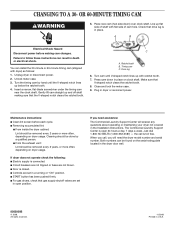
.... I START button has been pushed firmly. I From the exhaust vent: Lint should be removed every 2 years, or more often, depending on dryer usage. Ratchet tooth B. Timing cam C. I Clean lint screen before making sure that gas supply shutoff valves are set in a running or "ON... the meter case. 9. Maintenance instructions: I Controls are set in open 24 hours a day, 7 days a week. You can result in the dryer door well. 8563800B © 2008. Gently lift cam straight up below the ratchet tooth. 4. the call , you need assistance: The Commercial Laundry Support...
.... I START button has been pushed firmly. I From the exhaust vent: Lint should be removed every 2 years, or more often, depending on dryer usage. Ratchet tooth B. Timing cam C. I Clean lint screen before making sure that gas supply shutoff valves are set in a running or "ON... the meter case. 9. Maintenance instructions: I Controls are set in open 24 hours a day, 7 days a week. You can result in the dryer door well. 8563800B © 2008. Gently lift cam straight up below the ratchet tooth. 4. the call , you need assistance: The Commercial Laundry Support...


