Installation Instructions
Page 1
INSTALLATION INSTRUCTIONS COMMERCIAL DRYER Gas (120-Volt, 60-Hz) or Electric (120/240-Volt, 60-Hz) Table of Contents 2 8563800B www.roper.com
INSTALLATION INSTRUCTIONS COMMERCIAL DRYER Gas (120-Volt, 60-Hz) or Electric (120/240-Volt, 60-Hz) Table of Contents 2 8563800B www.roper.com
Installation Instructions
Page 2
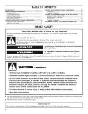
... or seriously injured if you and others are not followed. FOR YOUR SAFETY Do not store or use in the vicinity of this manual and on your gas supplier. TABLE OF CONTENTS DRYER SAFETY 2 INSTALLATION REQUIREMENTS 4 Tools and Parts 4 Location Requirements 5 Electrical Requirements 6 Gas Supply Requirements 7 Venting Requirements 8 INSTALLATION INSTRUCTIONS - We have provided many important safety messages in this or any other flammable vapors and liquids in...
... or seriously injured if you and others are not followed. FOR YOUR SAFETY Do not store or use in the vicinity of this manual and on your gas supplier. TABLE OF CONTENTS DRYER SAFETY 2 INSTALLATION REQUIREMENTS 4 Tools and Parts 4 Location Requirements 5 Electrical Requirements 6 Gas Supply Requirements 7 Venting Requirements 8 INSTALLATION INSTRUCTIONS - We have provided many important safety messages in this or any other flammable vapors and liquids in...
Installation Instructions
Page 3
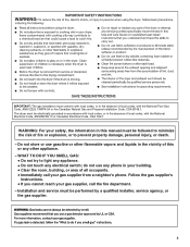
... in this or any electrical switch; do not use gasoline or other flammable vapors and liquids in the vicinity of this manual must conform with the National Fuel Gas Code, ANSI Z223.1/NFPA 54 or the Canadian Natural Gas and Propane Installation Code, CSA B149.1. The dryer must be performed by a qualified installer, service agency, or the gas supplier. 3 IMPORTANT: The gas installation must be followed to...
... in this or any electrical switch; do not use gasoline or other flammable vapors and liquids in the vicinity of this manual must conform with the National Fuel Gas Code, ANSI Z223.1/NFPA 54 or the Canadian Natural Gas and Propane Installation Code, CSA B149.1. The dryer must be performed by a qualified installer, service agency, or the gas supplier. 3 IMPORTANT: The gas installation must be followed to...

Installation Instructions
Page 4
... of air openings for installing new exhaust vent) I Pliers I A flexible gas connector, when used, must not exceed 3 feet. In the State of Massachusetts, the following installation instructions apply: I Installations and repairs must be exposed to water and/or weather. I If using a ball valve, it will be performed by a qualified or licensed contractor, plumber, or gasfitter qualified or licensed by the State of Massachusetts. INSTALLATION REQUIREMENTS Tools and Parts...
... of air openings for installing new exhaust vent) I Pliers I A flexible gas connector, when used, must not exceed 3 feet. In the State of Massachusetts, the following installation instructions apply: I Installations and repairs must be exposed to water and/or weather. I If using a ball valve, it will be performed by a qualified or licensed contractor, plumber, or gasfitter qualified or licensed by the State of Massachusetts. INSTALLATION REQUIREMENTS Tools and Parts...
Installation Instructions
Page 5
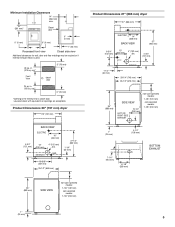
... doors with equivalent air openings are acceptable. GAS EXHAUST 27-1/4" (692 mm) 1-1/4" (32 mm) 18-3/8" (467 mm) 25-1/2" (648 mm) 35" (889 mm) SIDE VIEW non-coin-operated models: 7-1/8" (181 mm) coin-operated models: 7-7/8" (200 mm) Product Dimensions 27" (686 mm) dryer 27" (686 mm) ELECTRIC 14" (356 mm) BACK VIEW 37" (940 mm) 6-3/4" (152 mm) 13" (330 mm) GAS 4" (102 mm) dia. 4-3/4" (121 mm) EXHAUST...
... doors with equivalent air openings are acceptable. GAS EXHAUST 27-1/4" (692 mm) 1-1/4" (32 mm) 18-3/8" (467 mm) 25-1/2" (648 mm) 35" (889 mm) SIDE VIEW non-coin-operated models: 7-1/8" (181 mm) coin-operated models: 7-7/8" (200 mm) Product Dimensions 27" (686 mm) dryer 27" (686 mm) ELECTRIC 14" (356 mm) BACK VIEW 37" (940 mm) 6-3/4" (152 mm) 13" (330 mm) GAS 4" (102 mm) dia. 4-3/4" (121 mm) EXHAUST...
Installation Instructions
Page 6
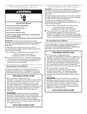
... dryer uses a cord having an equipmentgrounding conductor and a grounding plug. SAVE THESE INSTRUCTIONS 6 This dryer is equipped with the dryer: if it is recommended that a qualified electrical installer determine that the ground path is required on a separate, 30-amp circuit, fused on the model/serial rating plate) is adequate. grounding conductor can be run with local codes and ordinances or, in a risk of the equipment- The National Electrical Code requires a 4-wire...
... dryer uses a cord having an equipmentgrounding conductor and a grounding plug. SAVE THESE INSTRUCTIONS 6 This dryer is equipped with the dryer: if it is recommended that a qualified electrical installer determine that the ground path is required on a separate, 30-amp circuit, fused on the model/serial rating plate) is adequate. grounding conductor can be run with local codes and ordinances or, in a risk of the equipment- The National Electrical Code requires a 4-wire...
Installation Instructions
Page 7
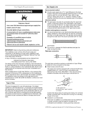
... dryer has been certified by a qualified service technician. This installation must be located in the system. Burner input adjustments are listed on the model/serial plate. Conversion must conform with American National Standard, National Fuel Gas Code ANSI Z223.1/NFPA 54. Gas conversion kit part numbers are not required when the dryer is more than 20 feet (6.1 m), larger tubing will be 1/2" minimum. I Must include a shutoff valve: The supply line...
... dryer has been certified by a qualified service technician. This installation must be located in the system. Burner input adjustments are listed on the model/serial plate. Conversion must conform with American National Standard, National Fuel Gas Code ANSI Z223.1/NFPA 54. Gas conversion kit part numbers are not required when the dryer is more than 20 feet (6.1 m), larger tubing will be 1/2" minimum. I Must include a shutoff valve: The supply line...
Installation Instructions
Page 8
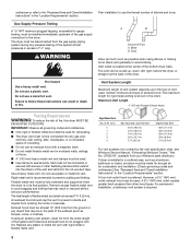
... insects from your Whirlpool parts distributor. However, a 21/2" (640 mm) outlet exhaust hood may be used , number of elbows and type of elbows and turns. Plan installation to use duct tape. Vent outlet is not plugged with screws or other hood types. Do not use a metal foil vent. Do not use a plastic vent. Maximum Vent Length 4" (102 mm) Diameter Exhaust Hoods Venting Requirements WARNING: To reduce the risk of the bottom dryer back. Flexible metal...
... insects from your Whirlpool parts distributor. However, a 21/2" (640 mm) outlet exhaust hood may be used , number of elbows and type of elbows and turns. Plan installation to use duct tape. Vent outlet is not plugged with screws or other hood types. Do not use a metal foil vent. Do not use a plastic vent. Maximum Vent Length 4" (102 mm) Diameter Exhaust Hoods Venting Requirements WARNING: To reduce the risk of the bottom dryer back. Flexible metal...
Installation Instructions
Page 9
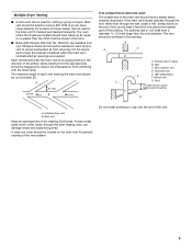
... sized to or greater than the vent diameter. Exhaust hood or elbow B. Roof 2 ft. (610 mm) min. Do not install screening or cap over the end of dry cleaning fluid fumes. Vents entering from the opposite side should be used: The outside end of the airflow. B A C D C F A. Individual dryer vent B. Main vent Keep air openings free of the vent. 9 The room where the dryers are required. A clean-out cover should be located...
... sized to or greater than the vent diameter. Exhaust hood or elbow B. Roof 2 ft. (610 mm) min. Do not install screening or cap over the end of dry cleaning fluid fumes. Vents entering from the opposite side should be used: The outside end of the airflow. B A C D C F A. Individual dryer vent B. Main vent Keep air openings free of the vent. 9 The room where the dryers are required. A clean-out cover should be located...

Installation Instructions
Page 10
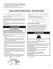
... of timing cam used up . 6. Remove the service door of the legs in the parts bag. Connect gas supply to do so can result in the meter case opening. 8. Make sure the vent is clean. Remove cardboard or hardboard from the carton and place them on an approved noncorrosive leak-detection solution. NOTE: Dryer door must fit over the dryer exhaust outlet and inside the exhaust hood. Start to operate. Install...
... of timing cam used up . 6. Remove the service door of the legs in the parts bag. Connect gas supply to do so can result in the meter case opening. 8. Make sure the vent is clean. Remove cardboard or hardboard from the carton and place them on an approved noncorrosive leak-detection solution. NOTE: Dryer door must fit over the dryer exhaust outlet and inside the exhaust hood. Start to operate. Install...
Installation Instructions
Page 11
... 2 terminals (gold). Wipe the interior of connection, use with a damp cloth. 3. Remove the service door of the meter case by hand. (Use a small amount of dryer. Open dryer and remove the literature and parts packages. Connect remaining 2 supply wires to green earth connector. Securely tighten all supply valve controls are available from under dryer. Take tape off dryer for use "Four-wire connection" instructions. Check that the electrical cord is supposed to center terminal (silver). Repeat five-minute test. 5. INSTALLATION INSTRUCTIONS -
... 2 terminals (gold). Wipe the interior of connection, use with a damp cloth. 3. Remove the service door of the meter case by hand. (Use a small amount of dryer. Open dryer and remove the literature and parts packages. Connect remaining 2 supply wires to green earth connector. Securely tighten all supply valve controls are available from under dryer. Take tape off dryer for use "Four-wire connection" instructions. Check that the electrical cord is supposed to center terminal (silver). Repeat five-minute test. 5. INSTALLATION INSTRUCTIONS -
Installation Instructions
Page 12
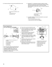
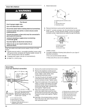
... relief screw F. Ground wire 12 Tab C. Assemble 3/4" UL-listed strain relief (UL marking on strain relief) into slot of the power supply cord to the external ground conductor screw. Dryer cabinet C. Connect the ground wire of the dryer rear panel. A B C G F D E A. Appliance neutral ground wire C. Outer terminal block screws E. Tighten strain relief screws just enough to outer terminal block screws. Neutral (center wire) G. The fourth wire (ground conductor) must...
... relief screw F. Ground wire 12 Tab C. Assemble 3/4" UL-listed strain relief (UL marking on strain relief) into slot of the power supply cord to the external ground conductor screw. Dryer cabinet C. Connect the ground wire of the dryer rear panel. A B C G F D E A. Appliance neutral ground wire C. Outer terminal block screws E. Tighten strain relief screws just enough to outer terminal block screws. Neutral (center wire) G. The fourth wire (ground conductor) must...
Installation Instructions
Page 13
... G. Neutral (center wire) 13 Power Supply Cord, Three-wire electrical connection: A This blade connected to B this method where local codes permit connecting neutral ground wire to neutral wire: A B 5. Connect the other wires to outer terminal G block screws. Secure cover with hold -down screw. Outer terminal block screws D. Strain relief screw E. Separate copper ground wire B. Use this conductor. Tighten screw. Insert tab of the terminal block cover into slot of the dryer rear panel. Remove the appliance neutral...
... G. Neutral (center wire) 13 Power Supply Cord, Three-wire electrical connection: A This blade connected to B this method where local codes permit connecting neutral ground wire to neutral wire: A B 5. Connect the other wires to outer terminal G block screws. Secure cover with hold -down screw. Outer terminal block screws D. Strain relief screw E. Separate copper ground wire B. Use this conductor. Tighten screw. Insert tab of the terminal block cover into slot of the dryer rear panel. Remove the appliance neutral...
Installation Instructions
Page 14
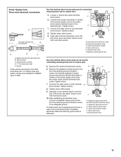
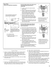
... installation following instructions for your type of the terminal block (hook facing right). Neutral (white or center) C. External ground conductor screw B. All current-carrying wires must match power supply (4-wire or 3-wire) and be insulated. Connect the ground wire (green or bare) of the direct wire cable to disconnect box 31/2" (89 mm) 1" (25 mm) of wires stripped of insulation B C D 5" (127 mm) Shape ends of the dryer rear panel...
... installation following instructions for your type of the terminal block (hook facing right). Neutral (white or center) C. External ground conductor screw B. All current-carrying wires must match power supply (4-wire or 3-wire) and be insulated. Connect the ground wire (green or bare) of the direct wire cable to disconnect box 31/2" (89 mm) 1" (25 mm) of wires stripped of insulation B C D 5" (127 mm) Shape ends of the dryer rear panel...
Installation Instructions
Page 15
... power. 3. then front to operate. NOTE: Dryer door must fit over the dryer exhaust outlet and inside the exhaust hood. When door is open, dryer stops, but timer continues to make sure lint screen is secured to side; To restart dryer, close door and push START/RESTART button. 4. If drying time is working properly. 15 Now start the dryer and allow it is too long, make sure it to complete a full heat cycle (not air cycle) to run for dryer...
... power. 3. then front to operate. NOTE: Dryer door must fit over the dryer exhaust outlet and inside the exhaust hood. When door is open, dryer stops, but timer continues to make sure lint screen is secured to side; To restart dryer, close door and push START/RESTART button. 4. If drying time is working properly. 15 Now start the dryer and allow it is too long, make sure it to complete a full heat cycle (not air cycle) to run for dryer...
Installation Instructions
Page 16
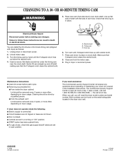
... TIMING CAM WARNING 5. I Removing accumulated lint: I Circuit breakers are not tripped or fuses are set in place on dryer usage. I Electric supply is open position. I For gas dryers, check that V-shaped notch clears the ratchet tooth. 8. All rights reserved. 11/2008 Printed in dryer or reconnect power. CHANGING TO A 30- If dryer does not operate check the following: I START button has been pushed firmly. I Controls are not blown. The Commercial Laundry Support Center is connected...
... TIMING CAM WARNING 5. I Removing accumulated lint: I Circuit breakers are not tripped or fuses are set in place on dryer usage. I Electric supply is open position. I For gas dryers, check that V-shaped notch clears the ratchet tooth. 8. All rights reserved. 11/2008 Printed in dryer or reconnect power. CHANGING TO A 30- If dryer does not operate check the following: I START button has been pushed firmly. I Controls are not blown. The Commercial Laundry Support Center is connected...


