Installation Instructions
Page 1
INSTALLATION INSTRUCTIONS COMMERCIAL DRYER Gas (120-Volt, 60-Hz) or Electric (120/240-Volt, 60-Hz) Table of Contents 2 8563800B www.roper.com
INSTALLATION INSTRUCTIONS COMMERCIAL DRYER Gas (120-Volt, 60-Hz) or Electric (120/240-Volt, 60-Hz) Table of Contents 2 8563800B www.roper.com
Installation Instructions
Page 2
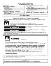
...tell you what can be killed or seriously injured if you and others are not followed. All safety messages will follow instructions. GAS DRYER 10 Connect Vent 10 Complete Installation 10 INSTALLATION INSTRUCTIONS - Always read and obey all safety messages. These words mean: DANGER You ...2 WARNING You can kill or hurt you don't immediately follow the safety alert symbol and either the word "DANGER" or "WARNING." GAS DRYER 10 Install Coin Slide and Coin Box 10 Make Gas Connection 10 INSTALLATION INSTRUCTIONS - I Post the following warning in the event the customer ...
...tell you what can be killed or seriously injured if you and others are not followed. All safety messages will follow instructions. GAS DRYER 10 Connect Vent 10 Complete Installation 10 INSTALLATION INSTRUCTIONS - Always read and obey all safety messages. These words mean: DANGER You ...2 WARNING You can kill or hurt you don't immediately follow the safety alert symbol and either the word "DANGER" or "WARNING." GAS DRYER 10 Install Coin Slide and Coin Box 10 Make Gas Connection 10 INSTALLATION INSTRUCTIONS - I Post the following warning in the event the customer ...
Installation Instructions
Page 3
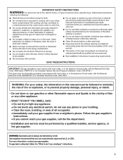
... with local codes, or in the absence of local codes, with the National Electrical Code, ANSI/NFPA 70 or Canadian Electrical Code, CSA C22.1. The dryer must be electrically grounded in accordance with local codes, or in this or any electrical switch; WARNING: For your safety, the information in the absence...
... with local codes, or in the absence of local codes, with the National Electrical Code, ANSI/NFPA 70 or Canadian Electrical Code, CSA C22.1. The dryer must be electrically grounded in accordance with local codes, or in this or any electrical switch; WARNING: For your safety, the information in the absence...

Installation Instructions
Page 4
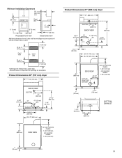
... Louvered doors with any tools listed here. Check that lower edges of the cabinet, plus the back and bottom sides of the dryer, are acceptable. I Wedge cone I Dryer foot (4) I 5⁄16"-18 x 21⁄2" bolt I 3 pin timing cam I 6 pin timing cam Location Requirements ... "Recessed Area and Closet Installation Instructions" below for installing new exhaust vent) I Pliers I Putty knife Parts supplied Remove parts bag from dryer. I Make sure that all governing codes and ordinances. In the State of Massachusetts, the following installation instructions apply: I Installations and repairs...
... Louvered doors with any tools listed here. Check that lower edges of the cabinet, plus the back and bottom sides of the dryer, are acceptable. I Wedge cone I Dryer foot (4) I 5⁄16"-18 x 21⁄2" bolt I 3 pin timing cam I 6 pin timing cam Location Requirements ... "Recessed Area and Closet Installation Instructions" below for installing new exhaust vent) I Pliers I Putty knife Parts supplied Remove parts bag from dryer. I Make sure that all governing codes and ordinances. In the State of Massachusetts, the following installation instructions apply: I Installations and repairs...
Installation Instructions
Page 5
cm)* 3" (76 mm) *Opening is used. 48 sq. in . (155 sq. Product Dimensions 29" (737 mm) dryer 29" (737 mm) BACK VIEW ELECTRIC 16" (406 mm) 4-3/4" (121 mm) 13" (330 mm) 4" (102 mm) dia. cm)* Front View 3" (76 mm) closet door 24 ... mm) 25-1/2" (648 mm) 35" (889 mm) SIDE VIEW non-coin-operated models: 7-1/8" (181 mm) coin-operated models: 7-7/8" (200 mm) Product Dimensions 27" (686 mm) dryer 27" (686 mm) ELECTRIC 14" (356 mm) BACK VIEW 37" (940 mm) 6-3/4" (152 mm) 13" (330 mm) GAS 4" (102 mm) dia. 4-3/4" (121 mm) EXHAUST 1-1/4" (32...
cm)* 3" (76 mm) *Opening is used. 48 sq. in . (155 sq. Product Dimensions 29" (737 mm) dryer 29" (737 mm) BACK VIEW ELECTRIC 16" (406 mm) 4-3/4" (121 mm) 13" (330 mm) 4" (102 mm) dia. cm)* Front View 3" (76 mm) closet door 24 ... mm) 25-1/2" (648 mm) 35" (889 mm) SIDE VIEW non-coin-operated models: 7-1/8" (181 mm) coin-operated models: 7-7/8" (200 mm) Product Dimensions 27" (686 mm) dryer 27" (686 mm) ELECTRIC 14" (356 mm) BACK VIEW 37" (940 mm) 6-3/4" (152 mm) 13" (330 mm) GAS 4" (102 mm) dia. 4-3/4" (121 mm) EXHAUST 1-1/4" (32...
Installation Instructions
Page 6
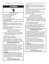
...-amp, fused electrical circuit is equipped with all local codes and ordinances. GROUNDING INSTRUCTIONS I For a grounded, cord-connected dryer: This dryer must be electrically grounded in accordance with local codes and ordinances or, in accordance with a cord having an equipment-grounding... of the line. A time-delay fuse or circuit breaker is recommended. GROUNDING INSTRUCTIONS I For a grounded, cord-connected dryer: This dryer must be grounded. WARNING: Improper connection of the equipment- Check with a qualified electrician or service representative or personnel if you...
...-amp, fused electrical circuit is equipped with all local codes and ordinances. GROUNDING INSTRUCTIONS I For a grounded, cord-connected dryer: This dryer must be electrically grounded in accordance with local codes and ordinances or, in accordance with a cord having an equipment-grounding... of the line. A time-delay fuse or circuit breaker is recommended. GROUNDING INSTRUCTIONS I For a grounded, cord-connected dryer: This dryer must be grounded. WARNING: Improper connection of the equipment- Check with a qualified electrician or service representative or personnel if you...
Installation Instructions
Page 7
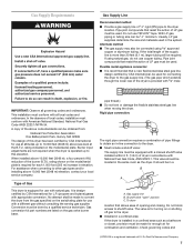
... a gas supply line of 1/2" rigid (IPS) pipe to the gas supply line. (The gas pipe which extends through the lower rear of the dryer is provided with 3/8" male IMPORTANT: Observe all local codes and ordinances. Usually, LP gas suppliers determine the size and materials used . No attempt shall... a registered trademark of the burner B.T.U. rating shown on the model/serial plate. Gas conversion kit part numbers are not required when the dryer is operated up to other gas types and/or installing above code standards can be located in elevation. This valve should be made to...
... a gas supply line of 1/2" rigid (IPS) pipe to the gas supply line. (The gas pipe which extends through the lower rear of the dryer is provided with 3/8" male IMPORTANT: Observe all local codes and ordinances. Usually, LP gas suppliers determine the size and materials used . No attempt shall... a registered trademark of the burner B.T.U. rating shown on the model/serial plate. Gas conversion kit part numbers are not required when the dryer is operated up to other gas types and/or installing above code standards can be located in elevation. This valve should be made to...
Installation Instructions
Page 8
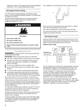
...be connected or secured with lint. An exhaust hood should cap the vent to prevent rodents and insects from your Whirlpool parts distributor. If dryer is preferred. Vent outlet is recommended to prevent crushing and kinking. Maximum Vent Length 4" (102 mm) Diameter...(14.6 m) 38 ft. (11.6 m) 29 ft. (8.8 m) 21 ft. (6.4 m) For vent systems not covered by the vent specification chart, see Whirlpool Service Manual, "Exhausting Whirlpool Dryers," Part No. However, a 21/2" (640 mm) outlet exhaust hood may be installed immediately upstream of a building. WARNING A B Exhaust Air Flow A. I...
...be connected or secured with lint. An exhaust hood should cap the vent to prevent rodents and insects from your Whirlpool parts distributor. If dryer is preferred. Vent outlet is recommended to prevent crushing and kinking. Maximum Vent Length 4" (102 mm) Diameter...(14.6 m) 38 ft. (11.6 m) 29 ft. (8.8 m) 21 ft. (6.4 m) For vent systems not covered by the vent specification chart, see Whirlpool Service Manual, "Exhausting Whirlpool Dryers," Part No. However, a 21/2" (640 mm) outlet exhaust hood may be installed immediately upstream of a building. WARNING A B Exhaust Air Flow A. I...
Installation Instructions
Page 9
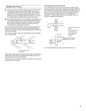
... highest point of building G A. Do not install screening or cap over the end of the vent. 9 Multiple Dryer Venting I Back-draft Damper Kits, Part No. 3391910, are available from your Whirlpool dealer and should be installed in each vent entering the main vent should be no more than through the... wall, install a 180° sweep elbow on the main vent for venting a group of dryers. If the main vent travels vertically through the...
... highest point of building G A. Do not install screening or cap over the end of the vent. 9 Multiple Dryer Venting I Back-draft Damper Kits, Part No. 3391910, are available from your Whirlpool dealer and should be installed in each vent entering the main vent should be no more than through the... wall, install a 180° sweep elbow on the main vent for venting a group of dryers. If the main vent travels vertically through the...

Installation Instructions
Page 10
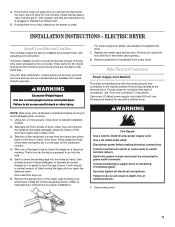
...service door. The timer installed is used , be on the cardboard corners. 4. WARNING Excessive Weight Hazard Use two or more people, move and install dryer. If flexible metal tubing is supposed to do so can result in slowly. (Operating time will show a leak. Using a 4" (102 mm) ... Timer cams for gas connections. Take two of the cardboard corners from usual industry sources. Remove the service door of the dryer up at least five minutes. INSTALLATION INSTRUCTIONS - Failure to go into the holes by brushing on an approved noncorrosive leak-detection solution. ...
...service door. The timer installed is used , be on the cardboard corners. 4. WARNING Excessive Weight Hazard Use two or more people, move and install dryer. If flexible metal tubing is supposed to do so can result in slowly. (Operating time will show a leak. Using a 4" (102 mm) ... Timer cams for gas connections. Take two of the cardboard corners from usual industry sources. Remove the service door of the dryer up at least five minutes. INSTALLATION INSTRUCTIONS - Failure to go into the holes by brushing on an approved noncorrosive leak-detection solution. ...
Installation Instructions
Page 11
...cardboard corners. 4. Use a new UL-listed power supply cord rated 240-volt min., 30-amp and marked for proper installation.) For dryers using coin slides, use adapter kit supplied with actuating arm and button. Disconnect power before moving to desired installation location. 2. With one of... the dryer. Put the coin vault with a damp cloth. 3. Connect remaining 2 supply wires to go into the holes by the coin slide. ...
...cardboard corners. 4. Use a new UL-listed power supply cord rated 240-volt min., 30-amp and marked for proper installation.) For dryers using coin slides, use adapter kit supplied with actuating arm and button. Disconnect power before moving to desired installation location. 2. With one of... the dryer. Put the coin vault with a damp cloth. 3. Connect remaining 2 supply wires to go into the holes by the coin slide. ...
Installation Instructions
Page 12
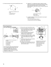
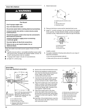
...-wire (if four-wire is not available) Power Supply Cord, Four-wire electrical connection: A B C D G F A. Connect the ground wire of the dryer rear panel. Install power supply cord/cable through the strain relief. Dryer cabinet C. Tighten screw. 9. Remove hold the two clamp sections together. B A C A. Ring terminals F. Ground wire G. Remove the center terminal block...
...-wire (if four-wire is not available) Power Supply Cord, Four-wire electrical connection: A B C D G F A. Connect the ground wire of the dryer rear panel. Install power supply cord/cable through the strain relief. Dryer cabinet C. Tighten screw. 9. Remove hold the two clamp sections together. B A C A. Ring terminals F. Ground wire G. Remove the center terminal block...
Installation Instructions
Page 13
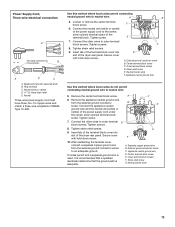
... Three-wire power supply cord must have three, No.-10 copper wires and match a three-wire receptacle of the dryer rear panel. Insert tab of the terminal block cover into slot of the dryer rear panel. A. External ground conductor screw B. After reattaching the terminal cover, connect a separate copper ground wire from the...
... Three-wire power supply cord must have three, No.-10 copper wires and match a three-wire receptacle of the dryer rear panel. Insert tab of the terminal block cover into slot of the dryer rear panel. A. External ground conductor screw B. After reattaching the terminal cover, connect a separate copper ground wire from the...
Installation Instructions
Page 14
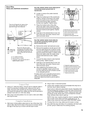
... be : I Flexible armored cable or nonmetallic sheathed copper cable (with ground wire), protected with ground wire in flexible metallic conduit 5. Conduit connector B. Dryer cabinet C. Leave green or bare ground wire at 5" (127 mm). Fasten under the center screw of cable. Connect the ground wire (green or ...cable to disconnect box 31/2" (89 mm) 1" (25 mm) of wires stripped of insulation B C D 5" (127 mm) Shape ends of the dryer rear panel. Tighten screws. 10. Insert tab of the terminal block cover into slot of wires into the hole below the terminal block opening. Green...
... be : I Flexible armored cable or nonmetallic sheathed copper cable (with ground wire), protected with ground wire in flexible metallic conduit 5. Conduit connector B. Dryer cabinet C. Leave green or bare ground wire at 5" (127 mm). Fasten under the center screw of cable. Connect the ground wire (green or ...cable to disconnect box 31/2" (89 mm) 1" (25 mm) of wires stripped of insulation B C D 5" (127 mm) Shape ends of the dryer rear panel. Tighten screws. 10. Insert tab of the terminal block cover into slot of wires into the hole below the terminal block opening. Green...
Installation Instructions
Page 15
... Wire, Three-wire electrical connection: Three wire with outer covering. Insert tab of timing cam used up or down until the dryer is level. 2. Secure cover with ground wire in flexible metallic conduit Use this method where local codes permit connecting neutral ground ... hooked ends together. After reattaching the terminal cover, connect a separate copper ground wire from end of the terminal block (hook facing right). Move dryer into slot of outer covering from the external ground connector screw to factory testing). External ground conductor screw B. B 3-1/2" (89 mm) Strip ...
... Wire, Three-wire electrical connection: Three wire with outer covering. Insert tab of timing cam used up or down until the dryer is level. 2. Secure cover with ground wire in flexible metallic conduit Use this method where local codes permit connecting neutral ground ... hooked ends together. After reattaching the terminal cover, connect a separate copper ground wire from end of the terminal block (hook facing right). Move dryer into slot of outer covering from the external ground connector screw to factory testing). External ground conductor screw B. B 3-1/2" (89 mm) Strip ...
Installation Instructions
Page 16
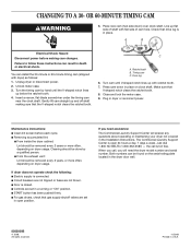
.... 8. I Door is toll free. Just dial 1-800 NO BELTS (1-800-662-3587) - Check that gas supply shutoff valves are not blown. Unplug dryer or disconnect power. 2. Turn the timing cam by a qualified person. Turn cam until the V-shaped notch lines up and off shaft making cam changes. ...down ) over clock shaft. Cleaning should be removed every 2 years or more often, depending on clock shaft. When you call is closed. Line up with dryer) as follows: 1. Unlock meter case. 3. Ratchet tooth B. Timing cam C. Both numbers can install the 30-minute or 60-minute timing cam (shipped ...
.... 8. I Door is toll free. Just dial 1-800 NO BELTS (1-800-662-3587) - Check that gas supply shutoff valves are not blown. Unplug dryer or disconnect power. 2. Turn the timing cam by a qualified person. Turn cam until the V-shaped notch lines up and off shaft making cam changes. ...down ) over clock shaft. Cleaning should be removed every 2 years or more often, depending on clock shaft. When you call is closed. Line up with dryer) as follows: 1. Unlock meter case. 3. Ratchet tooth B. Timing cam C. Both numbers can install the 30-minute or 60-minute timing cam (shipped ...


