
Installation Instructions
Page 1
www.whirlpool.com Part No. 8527795 COMMERCIAL DRYER GAS ELECTRIC 120-volt, 60 Hz 120/240-volt, 60 Hz ® COMMERCIAL LAUNDRY PRODUCTS Installation Instructions IMPORTANT: Read and save these instructions IMPORTANT Installer: Leave Installation Instructions with the owner. Save Installation Instructions for future reference. Owner: Keep Installation Instructions for local electrical inspector's use.
www.whirlpool.com Part No. 8527795 COMMERCIAL DRYER GAS ELECTRIC 120-volt, 60 Hz 120/240-volt, 60 Hz ® COMMERCIAL LAUNDRY PRODUCTS Installation Instructions IMPORTANT: Read and save these instructions IMPORTANT Installer: Leave Installation Instructions with the owner. Save Installation Instructions for future reference. Owner: Keep Installation Instructions for local electrical inspector's use.

Installation Instructions
Page 2
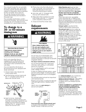
... or area of clothes dryers in published user-repair instructions that could cause a load to carry out. 9. Make sure you understand and have everything necessary for the customer's use fabric softeners or products to dry articles containing foam rubber or similarly textured rubber-like materials. 11. Properly install dryer. Exhaust to outdoors: Dryer must be obtained from service or discarded, remove the door to a chemical...
... or area of clothes dryers in published user-repair instructions that could cause a load to carry out. 9. Make sure you understand and have everything necessary for the customer's use fabric softeners or products to dry articles containing foam rubber or similarly textured rubber-like materials. 11. Properly install dryer. Exhaust to outdoors: Dryer must be obtained from service or discarded, remove the door to a chemical...
Installation Instructions
Page 3
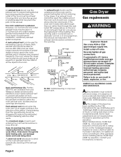
... by the exhaust length chart, see Whirlpool Service Manual, "Exhausting Whirlpool Dryers," Part No. 603197, available from entire length of drying time when activated by hand until "V" -shaped notch lines up , down in reduced air flow. Make sure that provides 45 minutes of the dryer. Do not use a metal foil vent. Replace any plastic or metal foil exhaust vent with actuating arm and button. EXHAUST HOOD TYPE 4" (10.2 cm) 4" (10.2 cm) No. To change to...
... by the exhaust length chart, see Whirlpool Service Manual, "Exhausting Whirlpool Dryers," Part No. 603197, available from entire length of drying time when activated by hand until "V" -shaped notch lines up , down in reduced air flow. Make sure that provides 45 minutes of the dryer. Do not use a metal foil vent. Replace any plastic or metal foil exhaust vent with actuating arm and button. EXHAUST HOOD TYPE 4" (10.2 cm) 4" (10.2 cm) No. To change to...
Installation Instructions
Page 4
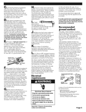
... in balance within the main exhaust vent. An exhaust hood should be located on the main exhaust vent for periodically cleaning of the exhaust system. Four-inch outlet hood is required. Large-capacity lint screens of the exhaust. dryer exhaust vent dryer exhaust vent 30° max. The exhaust vent should be staggered to reduce the exhausted air from returning into the dryers and to other gas types and/or installing above the highest part of the building. Securely...
... in balance within the main exhaust vent. An exhaust hood should be located on the main exhaust vent for periodically cleaning of the exhaust system. Four-inch outlet hood is required. Large-capacity lint screens of the exhaust. dryer exhaust vent dryer exhaust vent 30° max. The exhaust vent should be staggered to reduce the exhausted air from returning into the dryers and to other gas types and/or installing above the highest part of the building. Securely...
Installation Instructions
Page 5
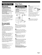
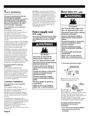
... installation, operation and servicing (if ever needed . If rigid pipe is used for combustion air. J. The dryer must be installed in the door well of air openings for connecting the dryer to the dryer. In the event of the gas supply piping system at test pressures in -line connection to the gas supply line. (The gas feed pipe which extends through the lower rear of the dryer is certified by a qualified electrician. 3-prong ground-type outlet 3-prong...
... installation, operation and servicing (if ever needed . If rigid pipe is used for combustion air. J. The dryer must be installed in the door well of air openings for connecting the dryer to the dryer. In the event of the gas supply piping system at test pressures in -line connection to the gas supply line. (The gas feed pipe which extends through the lower rear of the dryer is certified by a qualified electrician. 3-prong ground-type outlet 3-prong...
Installation Instructions
Page 6
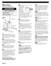
... factory testing). Close toe panel. All connections must be certain there are in slowly. (Operating time will accumulate per number of coins and type of the meter case. To exhaust dryer, see Exhaust requirements, Pages 3-4. If drying time is too long, make sure lint screen is plugged in back or other injury. 3-prong, ground-type outlet exhaust ventt gas supply line gas shutoff valve 1. Page 6 Firmly grasp the body of the drum thoroughly with dryer. Lift the service door...
... factory testing). Close toe panel. All connections must be certain there are in slowly. (Operating time will accumulate per number of coins and type of the meter case. To exhaust dryer, see Exhaust requirements, Pages 3-4. If drying time is too long, make sure lint screen is plugged in back or other injury. 3-prong, ground-type outlet exhaust ventt gas supply line gas shutoff valve 1. Page 6 Firmly grasp the body of the drum thoroughly with dryer. Lift the service door...
Installation Instructions
Page 7
... kit supplied with lock and key the meter case opening. 6. WARNING Excessive Weight Hazard Use two or more people to avoid damaging floor covering. exhaust vent system fuse disconnect box 30-amp outlet 5. Take tape off front corners of the meter case. With dryer in conformance with CAN 1-B149 installation codes** and all national or local codes. Lift the service door up . Replace the meter case service door. Remove...
... kit supplied with lock and key the meter case opening. 6. WARNING Excessive Weight Hazard Use two or more people to avoid damaging floor covering. exhaust vent system fuse disconnect box 30-amp outlet 5. Take tape off front corners of the meter case. With dryer in conformance with CAN 1-B149 installation codes** and all national or local codes. Lift the service door up . Replace the meter case service door. Remove...
Installation Instructions
Page 8
... or bare wire) must be connected to a grounded metal, permanent wiring system; Remove hold the two clamp sections together. marking on the appliance. Improper connection of electric shock. GROUNDING INSTRUCTIONS: This appliance must be connected to green ground connector. The plug must be plugged into the hole below terminal block opening. Do not modify the plug provided with a clothes dryer. only) Use a new UL-approved power supply cord rated 240-volt...
... or bare wire) must be connected to a grounded metal, permanent wiring system; Remove hold the two clamp sections together. marking on the appliance. Improper connection of electric shock. GROUNDING INSTRUCTIONS: This appliance must be connected to green ground connector. The plug must be plugged into the hole below terminal block opening. Do not modify the plug provided with a clothes dryer. only) Use a new UL-approved power supply cord rated 240-volt...

Installation Instructions
Page 9
... wire: 3-1/2" (8.9 cm) 3/4" U.L.listed strain relief to external ground conductor screw. Cut 1-1/2" (3.8 cm) from end of terminal block cover into a hook. 8. Shape ends of wires into slot of power supply cable under center, silver-colored terminal block screw. 6. Remove center terminal block screw. 5. Tighten screw. 8. Place the hooked end of the neutral wire (white or center) of the dryer rear panel. Squeeze hook end together. Page 9 Connect the other power supply cable wires...
... wire: 3-1/2" (8.9 cm) 3/4" U.L.listed strain relief to external ground conductor screw. Cut 1-1/2" (3.8 cm) from end of terminal block cover into a hook. 8. Shape ends of wires into slot of power supply cable under center, silver-colored terminal block screw. 6. Remove center terminal block screw. 5. Tighten screw. 8. Place the hooked end of the neutral wire (white or center) of the dryer rear panel. Squeeze hook end together. Page 9 Connect the other power supply cable wires...

Installation Instructions
Page 10
.... Squeeze hooked ends together. Wire is grounded through direct wire cable. 3/4" (1.9 cm) U.L.-listed strain relief to outer terminal block screws. Page 10 Where local codes permit connecting cabinet-ground conductor to this conductor. Tighten strain relief screws. 8. Secure cover with outer covering. Three-wire receptacle POWER SUPPLY CORD spade terminals with ground wire (Romex) NEUTRAL wire (white or center) 3-1/2" (8.9 cm) Strip 3-1/2" (8.9 cm) of outer covering from end of dryer rear panel...
.... Squeeze hooked ends together. Wire is grounded through direct wire cable. 3/4" (1.9 cm) U.L.-listed strain relief to outer terminal block screws. Page 10 Where local codes permit connecting cabinet-ground conductor to this conductor. Tighten strain relief screws. 8. Secure cover with outer covering. Three-wire receptacle POWER SUPPLY CORD spade terminals with ground wire (Romex) NEUTRAL wire (white or center) 3-1/2" (8.9 cm) Strip 3-1/2" (8.9 cm) of outer covering from end of dryer rear panel...

Installation Instructions
Page 11
... dryer is working properly. Tighten screw. 6. Tighten strain relief screws. 8. Connect exhaust vent to back. then front to dryer exhaust outlet and exhaust hood using 4" (10.2 cm) clamps. Check dryer operation (some accumulated time may be on top of the dryer, first side to operate. When door is open, dryer stops, but timer continues to run for dryer to side; Now start the dryer and allow it to complete a full heat cycle (not air cycle) to factory testing). Three-wire connection...
... dryer is working properly. Tighten screw. 6. Tighten strain relief screws. 8. Connect exhaust vent to back. then front to dryer exhaust outlet and exhaust hood using 4" (10.2 cm) clamps. Check dryer operation (some accumulated time may be on top of the dryer, first side to operate. When door is open, dryer stops, but timer continues to run for dryer to side; Now start the dryer and allow it to complete a full heat cycle (not air cycle) to factory testing). Three-wire connection...
Installation Instructions
Page 12
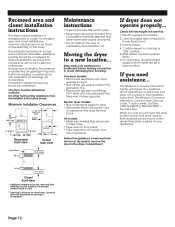
... external exhaust elbow is used. ** Opening is connected. 2. Minimum Installation Clearances 15" (38.1 cm)** 14" (35.6 cm) max. Electric dryer models: • Shut of gas pipe. Page 12 Louvered doors with equivalent air opening is acceptable. Circuit breakers are acceptable. The Whirlpool Consumer Interaction Center will need assistance... the call , you need the dryer model number and serial number. Tape end of dryer gas pipe. Controls are set in dryer base. • Tape drum to front panel. • Tape dryer door, lint screen and...
... external exhaust elbow is used. ** Opening is connected. 2. Minimum Installation Clearances 15" (38.1 cm)** 14" (35.6 cm) max. Electric dryer models: • Shut of gas pipe. Page 12 Louvered doors with equivalent air opening is acceptable. Circuit breakers are acceptable. The Whirlpool Consumer Interaction Center will need assistance... the call , you need the dryer model number and serial number. Tape end of dryer gas pipe. Controls are set in dryer base. • Tape drum to front panel. • Tape dryer door, lint screen and...
Installation Instructions
Page 13
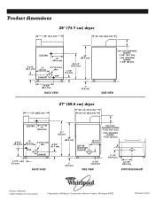
...) ELECTRIC 14" (35.6 cm) 37" (94 cm) 13" (33 cm) 4" (10.2 cm) dia. 4-3/4" (12.1 cm) 35" (88.9 cm) GAS LEFT OR RIGHT SIDE EXHAUST non-coinoperated models: 7-1/8" (18.1 cm) coin-operated models: 7-7/8" (20 cm) 10-1/4" (26 cm) 1-1/4" (3.2 cm) EXHAUST BACK VIEW 1" (2.5 cm) 4-1/4" (10.8 cm) SIDE VIEW 7-1/4" (18.4 cm) 14-1/8" (35.9 cm) BOTTOM EXHAUST Part No. 8527795 © 2001 Whirlpool Corporation Prepared by Whirlpool Corporation...
...) ELECTRIC 14" (35.6 cm) 37" (94 cm) 13" (33 cm) 4" (10.2 cm) dia. 4-3/4" (12.1 cm) 35" (88.9 cm) GAS LEFT OR RIGHT SIDE EXHAUST non-coinoperated models: 7-1/8" (18.1 cm) coin-operated models: 7-7/8" (20 cm) 10-1/4" (26 cm) 1-1/4" (3.2 cm) EXHAUST BACK VIEW 1" (2.5 cm) 4-1/4" (10.8 cm) SIDE VIEW 7-1/4" (18.4 cm) 14-1/8" (35.9 cm) BOTTOM EXHAUST Part No. 8527795 © 2001 Whirlpool Corporation Prepared by Whirlpool Corporation...
Parts List
Page 2
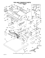
TOP AND CONSOLE PARTS For Model: CEM2750KQ0 (White) 8527791 2
TOP AND CONSOLE PARTS For Model: CEM2750KQ0 (White) 8527791 2
Parts List
Page 3
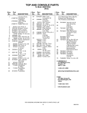
... CONSOLE PARTS For Model: CEM2750KQ0 (White) Illus. Part No. Part No. DESCRIPTION 1 Literature Parts LIT8527795 Instructions Installation LIT8315969 Label, Wiring Diagram LIT8527791 Repair Parts List 2 357213 Nut, Push−In 3 3361029 Bracket, Control 4 8316634 Panel, Control 5 8316516 Cap, End (R.H.) 6 3949734 Cap, End (L.H.) 7 97787 Screw, 11−16 x 3/4 8 3954665 Top 9 3347825 Plate−Mounting (2) 10 98445 Screw, 10−16 x 3/4 11 8316437 Switch, Pushbutton 12 3348109 Lens Light...
... CONSOLE PARTS For Model: CEM2750KQ0 (White) Illus. Part No. Part No. DESCRIPTION 1 Literature Parts LIT8527795 Instructions Installation LIT8315969 Label, Wiring Diagram LIT8527791 Repair Parts List 2 357213 Nut, Push−In 3 3361029 Bracket, Control 4 8316634 Panel, Control 5 8316516 Cap, End (R.H.) 6 3949734 Cap, End (L.H.) 7 97787 Screw, 11−16 x 3/4 8 3954665 Top 9 3347825 Plate−Mounting (2) 10 98445 Screw, 10−16 x 3/4 11 8316437 Switch, Pushbutton 12 3348109 Lens Light...

Parts List
Page 5
... Catch, Door Assembly 59 3398948 Wire, Jumper 60 3389522 Handle, Door 61 697215 Panel, Toe 62 3393657 Restrainer, Belt 64 3391408 Lever, Snap Switch 65 279731 4" − 90 Elbow Optional Parts Not Included Dryer Exhaust Kit (For Side & Bottom Venting) 66 279818 White 5 8527791 DESCRIPTION 1 3393008 Screw, 10−16 x 1/2 3 3391846 Clip, Front Panel (2) 4 3393258 Screw, 10−16 x 1/2 5 3394881 Switch, Broken Belt 6 3397659 Block, Terminal 7 8310656...
... Catch, Door Assembly 59 3398948 Wire, Jumper 60 3389522 Handle, Door 61 697215 Panel, Toe 62 3393657 Restrainer, Belt 64 3391408 Lever, Snap Switch 65 279731 4" − 90 Elbow Optional Parts Not Included Dryer Exhaust Kit (For Side & Bottom Venting) 66 279818 White 5 8527791 DESCRIPTION 1 3393008 Screw, 10−16 x 1/2 3 3391846 Clip, Front Panel (2) 4 3393258 Screw, 10−16 x 1/2 5 3394881 Switch, Broken Belt 6 3397659 Block, Terminal 7 8310656...

Parts List
Page 6
BULKHEAD PARTS For Model: CEM2750KQ0 (White) 8527791 6
BULKHEAD PARTS For Model: CEM2750KQ0 (White) 8527791 6

Parts List
Page 7
... 14 3387748 Element, Heater 15 697699 Shield, Heat 16 3387709 Nut, 3/8−16 (L.H.) 17 3387809 Bulkhead, Rear 18 3387459 Washer, Support 19 3399509 Shaft, L.H. Nos. 60 & 62) 53 697693 Baffle, Drum (3) 54 697557 Bulkhead, Front 58 8299979 Grill, Outlet 59 3390719 Thermal Fuse 60 697770 Seal, Cover Plate 62 697769 Seal, Lint Duct 64 3390721 Screen, Lint OPTIONAL PARTS (NOT INCLUDED) Illus. Thread 2 90767 Screw, 8−...
... 14 3387748 Element, Heater 15 697699 Shield, Heat 16 3387709 Nut, 3/8−16 (L.H.) 17 3387809 Bulkhead, Rear 18 3387459 Washer, Support 19 3399509 Shaft, L.H. Nos. 60 & 62) 53 697693 Baffle, Drum (3) 54 697557 Bulkhead, Front 58 8299979 Grill, Outlet 59 3390719 Thermal Fuse 60 697770 Seal, Cover Plate 62 697769 Seal, Lint Duct 64 3390721 Screen, Lint OPTIONAL PARTS (NOT INCLUDED) Illus. Thread 2 90767 Screw, 8−...


