Installation Instructions
Page 1
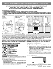
...are listed in this manual is located on the lower right front frame of the floor. 3. Fig. 1 Fig. 2 Fig. 3 30" *30" MINIMUM CLEARANCE BETWEEN THE TOP OF THE COOKING SURFACE AND THE BOTTOM OF AN UNPROTECTED WOOD OR METAL CABINET; Given dimensions provide minimum clearance.... the Installer • Read all instructions contained in these installation instructions before installing range. • Remove all packing material from the oven compartments before connecting the gas & electrical supply to the range. • Observe all governing codes and ordinances. • Be sure to the...
...are listed in this manual is located on the lower right front frame of the floor. 3. Fig. 1 Fig. 2 Fig. 3 30" *30" MINIMUM CLEARANCE BETWEEN THE TOP OF THE COOKING SURFACE AND THE BOTTOM OF AN UNPROTECTED WOOD OR METAL CABINET; Given dimensions provide minimum clearance.... the Installer • Read all instructions contained in these installation instructions before installing range. • Remove all packing material from the oven compartments before connecting the gas & electrical supply to the range. • Observe all governing codes and ordinances. • Be sure to the...
Installation Instructions
Page 4
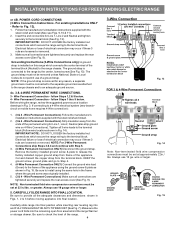
...the adequate clearances and dimensions shown in Fig. 15. IMPORTANT NOTE: DO NOT LOOSEN the factory installed nut connections which secure the range wiring to the range chassis. NOTE: For 3-Wire Permanent Connections skip Steps 3 & 4 and continue with the strain relief and install (Also see ...compression connections must be set at approximately 22in./ lbs. Always use 10 ga. Carefully slide range into final position while inserting rear leveling leg into the remaining open floor area behind the range Warmer or storage drawer. wire or larger. Grounding Instructions (3-Wire Connections...
...the adequate clearances and dimensions shown in Fig. 15. IMPORTANT NOTE: DO NOT LOOSEN the factory installed nut connections which secure the range wiring to the range chassis. NOTE: For 3-Wire Permanent Connections skip Steps 3 & 4 and continue with the strain relief and install (Also see ...compression connections must be set at approximately 22in./ lbs. Always use 10 ga. Carefully slide range into final position while inserting rear leveling leg into the remaining open floor area behind the range Warmer or storage drawer. wire or larger. Grounding Instructions (3-Wire Connections...
Parts Catalog
Page 1
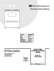
Model No. All rights reserved. BOX 212378 AUGUSTA, GA 30917 Publication No. WWEF3002K 5995532404 09/02/03 (EN/SERVICE/BJH) 369 Copyright © 2009 Electrolux Home Products, Inc. WWEF3002KWB Series 30" f/s elec Color white Market North America Wiring Diagram 316255306 Owner's Guide 316257134 Installation Instructions 316454912 30-INCH FREE- White-Westinghouse Product No. CRE3520G.eps L20G0056.eps L20V1118B.eps 316255306d.eps 316255306s.eps L20T0013.eps L20D0113.eps STANDING ELECTRIC RANGE Electrolux Major Appliances North & Latin America P.O.
Model No. All rights reserved. BOX 212378 AUGUSTA, GA 30917 Publication No. WWEF3002K 5995532404 09/02/03 (EN/SERVICE/BJH) 369 Copyright © 2009 Electrolux Home Products, Inc. WWEF3002KWB Series 30" f/s elec Color white Market North America Wiring Diagram 316255306 Owner's Guide 316257134 Installation Instructions 316454912 30-INCH FREE- White-Westinghouse Product No. CRE3520G.eps L20G0056.eps L20V1118B.eps 316255306d.eps 316255306s.eps L20T0013.eps L20D0113.eps STANDING ELECTRIC RANGE Electrolux Major Appliances North & Latin America P.O.