Owners Manual
Page 1
WIRELESS INTERCOM SYSTEMS AB IN USE LOCK POWER CALL TALK ™ ByPLiOneWar ER IN USE OFF ABC LOCK CALL TALK Owner's Manual For Wireless Intercom WHI-2C WHI-3C WHI-4C
WIRELESS INTERCOM SYSTEMS AB IN USE LOCK POWER CALL TALK ™ ByPLiOneWar ER IN USE OFF ABC LOCK CALL TALK Owner's Manual For Wireless Intercom WHI-2C WHI-3C WHI-4C
Owners Manual
Page 2
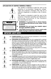
... sufficient magnitude to have a suitable outlet installed. This symbol is intended to alert the user to rain, water, or wet locations. To prevent fire or shock hazard, do not expose this device to the presence of important operating and maintenance (Servicing) instructions in a fire or electric shock. CLEANING Unplug the unit from the wall outlet before cleaning or...
... sufficient magnitude to have a suitable outlet installed. This symbol is intended to alert the user to rain, water, or wet locations. To prevent fire or shock hazard, do not expose this device to the presence of important operating and maintenance (Servicing) instructions in a fire or electric shock. CLEANING Unplug the unit from the wall outlet before cleaning or...

Owners Manual
Page 3
... the safety and operating instructions should use a mounting accessory recommended by the manufacturer. ACCESSORIES Do not place this can result in proper operating condition. Any mounting of fire or electric shock. SAFETY CHECK Upon completion of any service or repairs to this product, ask the service technician to perform safety checks to determine that the product is in a risk of...
... the safety and operating instructions should use a mounting accessory recommended by the manufacturer. ACCESSORIES Do not place this can result in proper operating condition. Any mounting of fire or electric shock. SAFETY CHECK Upon completion of any service or repairs to this product, ask the service technician to perform safety checks to determine that the product is in a risk of...
Owners Manual
Page 4
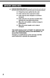
... been dropped or enclosure damaged. IMPORTANT SERVICE NOTES DAMAGE REQUIRING SERVICE Unplug the unit from the wall outlet and refer servicing to qualified service personnel under the following the operating instructions. If the unit has been exposed to operate the equipment. 2 Changes or modifications to the unit may void the users authority to water. When the power-supply cord or plug is damaged.
... been dropped or enclosure damaged. IMPORTANT SERVICE NOTES DAMAGE REQUIRING SERVICE Unplug the unit from the wall outlet and refer servicing to qualified service personnel under the following the operating instructions. If the unit has been exposed to operate the equipment. 2 Changes or modifications to the unit may void the users authority to water. When the power-supply cord or plug is damaged.
Owners Manual
Page 5
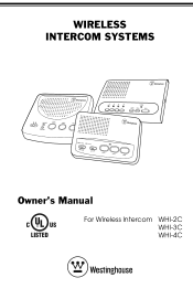
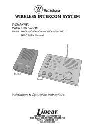
... of your new Wireless Intercom System! WIRELESS INTERCOM SYSTEM FEATURES Allows a choice of 2, 3 or 4 channels to talk to 1500 foot range. Compatible with all of rooms or offices. Please read these instructions carefully before installing your new Wireless Intercom System in simple steps how to install, use and care for your system and follow all Westinghouse Wireless Intercoms. Up to or monitor an unlimited number of the directions to ensure proper installation. This instruction manual explains in homes, offices...
... of your new Wireless Intercom System! WIRELESS INTERCOM SYSTEM FEATURES Allows a choice of 2, 3 or 4 channels to talk to 1500 foot range. Compatible with all of rooms or offices. Please read these instructions carefully before installing your new Wireless Intercom System in simple steps how to install, use and care for your system and follow all Westinghouse Wireless Intercoms. Up to or monitor an unlimited number of the directions to ensure proper installation. This instruction manual explains in homes, offices...
Owners Manual
Page 7
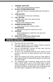
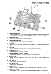
... monitoring, simply press the LOCK button. Also, if any other intercoms set to the desired channel using the CHANNEL SELECTOR button or switch. 3. OPERATING INSTRUCTIONS 1. Set the VOLUME/OFF controls on both units until the intercoms click on the same channel. 5. POWER/VOLUME SWITCH Turns unit on . 3. Plug each intercom unit to the same channel. 5. SPEAKER Clearly transmits pure, static-free, two-way voice communication. 9. Set each unit into an AC outlet. 2. IN USE & POWER INDICATORS Lights...
... monitoring, simply press the LOCK button. Also, if any other intercoms set to the desired channel using the CHANNEL SELECTOR button or switch. 3. OPERATING INSTRUCTIONS 1. Set the VOLUME/OFF controls on both units until the intercoms click on the same channel. 5. POWER/VOLUME SWITCH Turns unit on . 3. Plug each intercom unit to the same channel. 5. SPEAKER Clearly transmits pure, static-free, two-way voice communication. 9. Set each unit into an AC outlet. 2. IN USE & POWER INDICATORS Lights...
Installation Instructions
Page 1
WIRELESS INTERCOM SYSTEM 5-CHANNEL RADIO INTERCOM Models: WHDBI-5C (One Console & One Doorbell) WHI-5S (One Console) Doorbell Console Installation & Operation Instructions (760) 438-7000 • FAX (760) 438-7043 USA & Canada (800) 421-1587 & (800) 392-0123 Toll Free FAX (800) 468-1340 www.linearcorp.com
WIRELESS INTERCOM SYSTEM 5-CHANNEL RADIO INTERCOM Models: WHDBI-5C (One Console & One Doorbell) WHI-5S (One Console) Doorbell Console Installation & Operation Instructions (760) 438-7000 • FAX (760) 438-7043 USA & Canada (800) 421-1587 & (800) 392-0123 Toll Free FAX (800) 468-1340 www.linearcorp.com
Installation Instructions
Page 2
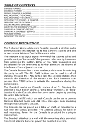
... controls the direction of interference from accessing the system. Two 9-volt alkaline batteries power the Doorbell intercom. TABLE OF CONTENTS CONSOLE FEATURES 1 DOORBELL FEATURES 2 PREPARE CONSOLE & ANTENNA 3 WALL MOUNTING THE DOORBELL 4 WALL MOUNTING THE CONSOLE 5 OPERATING THE DOORBELL & CONSOLE 6 OPERATING MULTIPLE CONSOLES 7 CALLING MULTIPLE CONSOLES 8 ADJUSTING THE DOORBELL'S VOLUME 9 CHANGING A CONSOLE'S SETTINGS 10 CHANGING A DOORBELL'S SETTINGS 11 TROUBLESHOOTING 12 IMPORTANT FCC NOTICE 13 CONSOLE DESCRIPTION The 5-channel Wireless Intercom Consoles...
... controls the direction of interference from accessing the system. Two 9-volt alkaline batteries power the Doorbell intercom. TABLE OF CONTENTS CONSOLE FEATURES 1 DOORBELL FEATURES 2 PREPARE CONSOLE & ANTENNA 3 WALL MOUNTING THE DOORBELL 4 WALL MOUNTING THE CONSOLE 5 OPERATING THE DOORBELL & CONSOLE 6 OPERATING MULTIPLE CONSOLES 7 CALLING MULTIPLE CONSOLES 8 ADJUSTING THE DOORBELL'S VOLUME 9 CHANGING A CONSOLE'S SETTINGS 10 CHANGING A DOORBELL'S SETTINGS 11 TROUBLESHOOTING 12 IMPORTANT FCC NOTICE 13 CONSOLE DESCRIPTION The 5-channel Wireless Intercom Consoles...
Installation Instructions
Page 3
... frequency. 1 All intercoms used in progress. ANTENNA Receives and sends the wireless intercom signals. ALL CALL BUTTON Press and hold to talk to be called . Antenna pivots for Console horizontal and vertical mounting. 5. VOLUME CONTROL - MUTE SWITCH When ON, the Console will be set to all stations. 11. STATION LABEL AREAS For applying labels that will not sound Doorbell Intercom chime tones or respond...
... frequency. 1 All intercoms used in progress. ANTENNA Receives and sends the wireless intercom signals. ALL CALL BUTTON Press and hold to talk to be called . Antenna pivots for Console horizontal and vertical mounting. 5. VOLUME CONTROL - MUTE SWITCH When ON, the Console will be set to all stations. 11. STATION LABEL AREAS For applying labels that will not sound Doorbell Intercom chime tones or respond...
Installation Instructions
Page 4
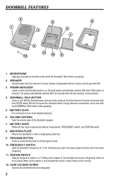
... intercom communication. 4. BATTERY CLIPS For connection to the mounting plate. 2 CASE LOCKING SCREW Secures the Doorbell to two 9-volt alkaline batteries. 6. MICROPHONE High-gain microphone monitors audio while the Doorbell's TALK button is on. Volume is pressed. VOLUME CONTROL Sets the volume level of the intercom Consoles (Consoles with the volume control (see Item #6). 3. BATTERY DOOR Slides off rear case to frequency "A" or "B". All intercoms used in the same system must be set...
... intercom communication. 4. BATTERY CLIPS For connection to the mounting plate. 2 CASE LOCKING SCREW Secures the Doorbell to two 9-volt alkaline batteries. 6. MICROPHONE High-gain microphone monitors audio while the Doorbell's TALK button is on. Volume is pressed. VOLUME CONTROL Sets the volume level of the intercom Consoles (Consoles with the volume control (see Item #6). 3. BATTERY DOOR Slides off rear case to frequency "A" or "B". All intercoms used in the same system must be set...
Installation Instructions
Page 5
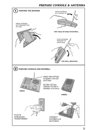
POINT ANTENNA STRAIGHT UP FROM CASE 2 PREPARE CONSOLE AND DOORBELL FOR WALL MOUNTING... CONSOLE LABELS ARE SUPPLIED TO IDENTIFY STATION LOCATIONS FACTORY SETTING: CONSOLE STATION #1 DOORBELL STATION #5 DOORBELL PLUG IN CONSOLE(S) TRANSFORMER CONNECT DOORBELL(S) BATTERIES 3 PREPARE CONSOLE & ANTENNA 1 PREPARE THE ANTENNA SWING ANTENNA ALL THE WAY UP SWING ANTENNA OUT FROM BOTTOM OF CASE FOR TABLE OR SHELF MOUNTING...
POINT ANTENNA STRAIGHT UP FROM CASE 2 PREPARE CONSOLE AND DOORBELL FOR WALL MOUNTING... CONSOLE LABELS ARE SUPPLIED TO IDENTIFY STATION LOCATIONS FACTORY SETTING: CONSOLE STATION #1 DOORBELL STATION #5 DOORBELL PLUG IN CONSOLE(S) TRANSFORMER CONNECT DOORBELL(S) BATTERIES 3 PREPARE CONSOLE & ANTENNA 1 PREPARE THE ANTENNA SWING ANTENNA ALL THE WAY UP SWING ANTENNA OUT FROM BOTTOM OF CASE FOR TABLE OR SHELF MOUNTING...

Installation Instructions
Page 6
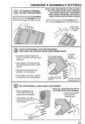
WALL MOUNTING THE DOORBELL NOTE: DO NOT MOUNT THE DOORBELL UNIT WHERE IT WILL BE EXPOSED TO EXCESSIVE MOISTURE, DUST, OR IN DIRECT SUNLIGHT 1 USE MOUNTING PLATE AND PENCIL TO MARK SCREW LOCATIONS 2 ATTACH MOUNTING PLATE USING THE SCREWS PROVIDED 3 TILT DOORBELL INTO MOUNTING PLATE 4 SECURE DOORBELL TO MOUNTING PLATE WITH THE CASE LOCKING SCREW NOTE: WAIT UNTIL AFTER ADJUSTING THE DOORBELL AUDIO VOLUME BEFORE FULLY TIGHTENING THE LOCKING SCREW 4
WALL MOUNTING THE DOORBELL NOTE: DO NOT MOUNT THE DOORBELL UNIT WHERE IT WILL BE EXPOSED TO EXCESSIVE MOISTURE, DUST, OR IN DIRECT SUNLIGHT 1 USE MOUNTING PLATE AND PENCIL TO MARK SCREW LOCATIONS 2 ATTACH MOUNTING PLATE USING THE SCREWS PROVIDED 3 TILT DOORBELL INTO MOUNTING PLATE 4 SECURE DOORBELL TO MOUNTING PLATE WITH THE CASE LOCKING SCREW NOTE: WAIT UNTIL AFTER ADJUSTING THE DOORBELL AUDIO VOLUME BEFORE FULLY TIGHTENING THE LOCKING SCREW 4
Installation Instructions
Page 8
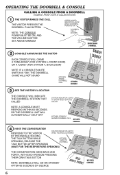
... CALLING KITCHEN 1 THE VISITOR MAKES THE CALL THE VISITOR PRESSES THE DOORBELL-TALK BUTTON NOTE: THE CONSOLE POWER MUST BE ON, AND THE VOLUME MUST BE SET ABOVE MINIMUM GREEN POWER INDICATOR LIGHTS WHILE DOORBELL POWER IS ON DOORBELL CALLS KITCHEN FRONT DOOR DOORBELL 2 CONSOLE ANNOUNCES THE VISITOR EACH CONSOLE WILL CHIME A "DING-DONG" (FOR STATION 5, FRONT DOOR) OR A "DONG" (FOR STATION...
... CALLING KITCHEN 1 THE VISITOR MAKES THE CALL THE VISITOR PRESSES THE DOORBELL-TALK BUTTON NOTE: THE CONSOLE POWER MUST BE ON, AND THE VOLUME MUST BE SET ABOVE MINIMUM GREEN POWER INDICATOR LIGHTS WHILE DOORBELL POWER IS ON DOORBELL CALLS KITCHEN FRONT DOOR DOORBELL 2 CONSOLE ANNOUNCES THE VISITOR EACH CONSOLE WILL CHIME A "DING-DONG" (FOR STATION 5, FRONT DOOR) OR A "DONG" (FOR STATION...

Installation Instructions
Page 9
OPERATING MULTIPLE CONSOLES CALLING ONE CONSOLE FROM ANOTHER CONSOLE EXAMPLE: GARAGE IS CALLING KITCHEN 1 CHOOSE WHOM TO CALL WITH CONSOLE POWER ON, PRESS THE BUTTON FOR THE CONSOLE THAT YOU WANT TO CALL (DOORBELLS CAN NOT BE CALLED) STATION INDICATOR LIGHTS GARAGE SELECTS KITCHEN GARAGE CONSOLE 2 MAKE THE CALL STATION INDICATOR STAYS LIT PRESS AND HOLD...
OPERATING MULTIPLE CONSOLES CALLING ONE CONSOLE FROM ANOTHER CONSOLE EXAMPLE: GARAGE IS CALLING KITCHEN 1 CHOOSE WHOM TO CALL WITH CONSOLE POWER ON, PRESS THE BUTTON FOR THE CONSOLE THAT YOU WANT TO CALL (DOORBELLS CAN NOT BE CALLED) STATION INDICATOR LIGHTS GARAGE SELECTS KITCHEN GARAGE CONSOLE 2 MAKE THE CALL STATION INDICATOR STAYS LIT PRESS AND HOLD...

Installation Instructions
Page 10
SPEAK TOWARDS THE CONSOLE ALL STATION INDICATORS LIGHT RELEASE THE ALL CALL BUTTON WHEN YOU ARE FINISHED TALKING NOTE: ANY CONSOLE WITH ITS MUTE SWITCH ON AND ANY DOORBELL UNITS THAT HAVE NOT BEEN USED IN THE PRIOR 60 SECONDS WILL NOT RECEIVE THE ALL-CALL MESSAGE KITCHEN CALLS ALL STATIONS ...CALLER BY PRESSING & HOLDING THE ALL CALL BUTTON WHILE SPEAKING, RELEASE THE ALL CALL BUTTON AFTER SPEAKING (WAIT FOR BEEP BEFORE TALKING) STATION INDICATOR LIGHTS WHILE TALKING AND LISTENING THE CONVERSATION GOES BACK AND FORTH, WITH EACH PERSON PRESSING THEIR OWN ALL CALL BUTTON CONSOLES WILL GO ON...
SPEAK TOWARDS THE CONSOLE ALL STATION INDICATORS LIGHT RELEASE THE ALL CALL BUTTON WHEN YOU ARE FINISHED TALKING NOTE: ANY CONSOLE WITH ITS MUTE SWITCH ON AND ANY DOORBELL UNITS THAT HAVE NOT BEEN USED IN THE PRIOR 60 SECONDS WILL NOT RECEIVE THE ALL-CALL MESSAGE KITCHEN CALLS ALL STATIONS ...CALLER BY PRESSING & HOLDING THE ALL CALL BUTTON WHILE SPEAKING, RELEASE THE ALL CALL BUTTON AFTER SPEAKING (WAIT FOR BEEP BEFORE TALKING) STATION INDICATOR LIGHTS WHILE TALKING AND LISTENING THE CONVERSATION GOES BACK AND FORTH, WITH EACH PERSON PRESSING THEIR OWN ALL CALL BUTTON CONSOLES WILL GO ON...

Installation Instructions
Page 11
ADJUSTING THE DOORBELL'S VOLUME THE DOORBELL'S VOLUME CAN BE ADJUSTED TO SUIT THE INSTALLATION HAVE SOMEONE TALK TO THE DOORBELL FROM THE CONSOLE WHILE ADJUSTING THE DOORBELL'S VOLUME DOORBELL VOLUME USE A SMALL SCREWDRIVER TO ADJUST THE VOLUME CONTROL LOW HIGH 9
ADJUSTING THE DOORBELL'S VOLUME THE DOORBELL'S VOLUME CAN BE ADJUSTED TO SUIT THE INSTALLATION HAVE SOMEONE TALK TO THE DOORBELL FROM THE CONSOLE WHILE ADJUSTING THE DOORBELL'S VOLUME DOORBELL VOLUME USE A SMALL SCREWDRIVER TO ADJUST THE VOLUME CONTROL LOW HIGH 9
Installation Instructions
Page 12
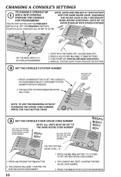
... FACTORY 1 ADD A NEW CONSOLE, PREPARE THE CONSOLE WITH THE SAME HOUSE CODE, CHANGING THE HOUSE CODE IS ONLY NECESSARY FOR PROGRAMMING WHEN ADDING ADDITIONAL UNITS OR TO THE FACTORY SETTING FOR THE FREQUENCY AVOID OVERLAP WITH OTHER SYSTEMS SWITCH IS "A", SET THE FREQUENCY SWITCHES TO MATCH ON ALL CONSOLES (ALL EITHER "A" OR "B") SET THE MUTE SWITCH TO OFF WHILE PROGRAMMING 1. THE SELECTED STATION NUMBER INDICATOR WILL FLASH SETTING THE CONSOLE'S STATION NUMBER NOTE: TO EXIT PROGRAMMING...
... FACTORY 1 ADD A NEW CONSOLE, PREPARE THE CONSOLE WITH THE SAME HOUSE CODE, CHANGING THE HOUSE CODE IS ONLY NECESSARY FOR PROGRAMMING WHEN ADDING ADDITIONAL UNITS OR TO THE FACTORY SETTING FOR THE FREQUENCY AVOID OVERLAP WITH OTHER SYSTEMS SWITCH IS "A", SET THE FREQUENCY SWITCHES TO MATCH ON ALL CONSOLES (ALL EITHER "A" OR "B") SET THE MUTE SWITCH TO OFF WHILE PROGRAMMING 1. THE SELECTED STATION NUMBER INDICATOR WILL FLASH SETTING THE CONSOLE'S STATION NUMBER NOTE: TO EXIT PROGRAMMING...
Installation Instructions
Page 13
... TIMES TO SET THE NEW HOUSE CODE NUMBER 2. RELEASE THE PROGRAM BUTTON (BE READY TO COUNT BEEPS) 4. BE SURE THE GREEN POWER LIGHT IS OFF (IF THE LIGHT IS ON, WAIT ABOUT 2 MINUTES) PROGRAM BUTTON INSIDE HOLE 2. USE AN OBJECT TO PRESS AND HOLD THE PROGRAM BUTTON UNTIL A BEEP SOUNDS 3. PRESS THE PROGRAM BUTTON TO EXIT PROGRAM MODE DOORBELL BEEPS THE NEW HOUSE CODE NUMBER 11 CHANGING A DOORBELL'S SETTINGS 1 TO CHANGE A DOORBELL OR ADD A NEW DOORBELL THE FACTORY SETTING FOR THE FREQUENCY SWITCH IS "A", SET...
... TIMES TO SET THE NEW HOUSE CODE NUMBER 2. RELEASE THE PROGRAM BUTTON (BE READY TO COUNT BEEPS) 4. BE SURE THE GREEN POWER LIGHT IS OFF (IF THE LIGHT IS ON, WAIT ABOUT 2 MINUTES) PROGRAM BUTTON INSIDE HOLE 2. USE AN OBJECT TO PRESS AND HOLD THE PROGRAM BUTTON UNTIL A BEEP SOUNDS 3. PRESS THE PROGRAM BUTTON TO EXIT PROGRAM MODE DOORBELL BEEPS THE NEW HOUSE CODE NUMBER 11 CHANGING A DOORBELL'S SETTINGS 1 TO CHANGE A DOORBELL OR ADD A NEW DOORBELL THE FACTORY SETTING FOR THE FREQUENCY SWITCH IS "A", SET...

Installation Instructions
Page 14
... ALKALINE BATTERIES KEEP CONSOLE AWAY FROM FLUORESCENT LIGHTS MOVE DOORBELL UNIT IF IT IS NEAR AN AC LINE BE SURE THE CONSOLE ANTENNA IS POINTED UP MOVE UNITS AROUND TO DETERMINE BETTER RECEPTION LOCATIONS CHANGE THE FREQUENCY SWITCHES ON EACH UNIT (ALL UNITS MUST BE ON THE SAME FREQUENCY) CHANGE THE HOUSE CODE MOVE UNITS AWAY FROM COMPUTERS, ELECTRIC MOTORS, LIGHT DIMMER SWITCHES, ETC. PERFORM THE SYSTEM PROGRAMMING AGAIN MOVE UNITS AWAY...
... ALKALINE BATTERIES KEEP CONSOLE AWAY FROM FLUORESCENT LIGHTS MOVE DOORBELL UNIT IF IT IS NEAR AN AC LINE BE SURE THE CONSOLE ANTENNA IS POINTED UP MOVE UNITS AROUND TO DETERMINE BETTER RECEPTION LOCATIONS CHANGE THE FREQUENCY SWITCHES ON EACH UNIT (ALL UNITS MUST BE ON THE SAME FREQUENCY) CHANGE THE HOUSE CODE MOVE UNITS AWAY FROM COMPUTERS, ELECTRIC MOTORS, LIGHT DIMMER SWITCHES, ETC. PERFORM THE SYSTEM PROGRAMMING AGAIN MOVE UNITS AWAY...
Installation Instructions
Page 15
...-located or operating in portable wireless signaling. IMPORTANT FCC NOTICE Radio controls provide a reliable communications link and fill an important need in conjunction with any interference received, including interference that occur on or near their operating frequencies, regardless of code settings. • Changes or modifications to the device may void FCC compliance. • Infrequently used radio links should be tested regularly to...
...-located or operating in portable wireless signaling. IMPORTANT FCC NOTICE Radio controls provide a reliable communications link and fill an important need in conjunction with any interference received, including interference that occur on or near their operating frequencies, regardless of code settings. • Changes or modifications to the device may void FCC compliance. • Infrequently used radio links should be tested regularly to...
