Installation Instructions
Page 1
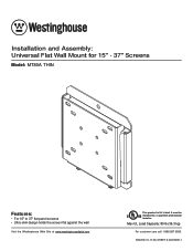
ISSUED: 01-17-06 SHEET #: 202-9090-1 Max UL Load Capacity: 80 lb (36.3 kg) For customer care call 1-866-287-5555. It must be installed by a qualified professional R installer. Installation and Assembly: Universal Flat Wall Mount for 15" - 37" Screens Model: MT80A THIN Features: • For 15" to 37" flat panel screens • Ultra-slim design holds the screen flat against the wall Visit the Westinghouse Web Site at www.westinghousedigital.com This product is UL Listed.
ISSUED: 01-17-06 SHEET #: 202-9090-1 Max UL Load Capacity: 80 lb (36.3 kg) For customer care call 1-866-287-5555. It must be installed by a qualified professional R installer. Installation and Assembly: Universal Flat Wall Mount for 15" - 37" Screens Model: MT80A THIN Features: • For 15" to 37" flat panel screens • Ultra-slim design holds the screen flat against the wall Visit the Westinghouse Web Site at www.westinghousedigital.com This product is UL Listed.
Installation Instructions
Page 2
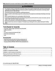
...installed by UL) Table of Contents Parts List ...3 Installation to Single Wood Stud Wall ...4 Installation to Solid Concrete or Cinder Block ...5 Attaching Hook Bracket to install your Westinghouse product until you have read and understood the instructions and warnings contained in this ...Installation Sheet. WARNING • Do not begin to Flat Panel Screen ...6 Installing and Removing Flat Panel Screen ...7 For customer care call ...
...installed by UL) Table of Contents Parts List ...3 Installation to Single Wood Stud Wall ...4 Installation to Solid Concrete or Cinder Block ...5 Attaching Hook Bracket to install your Westinghouse product until you have read and understood the instructions and warnings contained in this ...Installation Sheet. WARNING • Do not begin to Flat Panel Screen ...6 Installing and Removing Flat Panel Screen ...7 For customer care call ...
Installation Instructions
Page 7
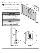
...Do not tighten screws with screws (C) can cause screen to come off of mount. Use additional man power or mechanical lifting equipment to 20 in figure 4.2 ...06 SHEET #: 202-9090-1 SCREEN A fig. 4.1 B A C fig. 4.2 7 of the screen. • Failure to mount. WARNING • Do not lift more weight than you can cause damage to lock hook bracket with excessive force. Note: For ...M5 x 12 mm screws (C) using 4 mm allen wrench (I) To remove screen from mount, loosen screws (C) and lift screen off mount if hit accidentally. Tighten M5 x 12 mm screws (C), shown in . • lb ...
...Do not tighten screws with screws (C) can cause screen to come off of mount. Use additional man power or mechanical lifting equipment to 20 in figure 4.2 ...06 SHEET #: 202-9090-1 SCREEN A fig. 4.1 B A C fig. 4.2 7 of the screen. • Failure to mount. WARNING • Do not lift more weight than you can cause damage to lock hook bracket with excessive force. Note: For ...M5 x 12 mm screws (C) using 4 mm allen wrench (I) To remove screen from mount, loosen screws (C) and lift screen off mount if hit accidentally. Tighten M5 x 12 mm screws (C), shown in . • lb ...