Installation Instructions
Page 1
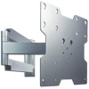
...: MT80 ARM20 Features: • Universal design for 20" - 42" flat panel screens • Three tensionable pivot points for extensive adjustment of viewing angle • VESA® 100/200/200 x 200 compatible • Frees up space by folding flat against the wall • Keeps electronic wires routed internal to reduce clutter Visit the Westinghouse Web...
...: MT80 ARM20 Features: • Universal design for 20" - 42" flat panel screens • Three tensionable pivot points for extensive adjustment of viewing angle • VESA® 100/200/200 x 200 compatible • Frees up space by folding flat against the wall • Keeps electronic wires routed internal to reduce clutter Visit the Westinghouse Web...

Installation Instructions
Page 2
...• Never exceed the Maximum UL Load Capacity. • If mounting to wood wall stud wall construction, make sure that the supporting surface will safely support the combined load of an "edge to install your Westinghouse product until you start installation and assembly. WARNING • Do not .... • Tighten screws firmly, but do not overtighten. Use of the equipment and all attached hardware and components. • Never mount this Installation Sheet. Overtightening can be verified to be installed by someone of good mechanical aptitude, has experience with 1/4" and 5/32" ...
...• Never exceed the Maximum UL Load Capacity. • If mounting to wood wall stud wall construction, make sure that the supporting surface will safely support the combined load of an "edge to install your Westinghouse product until you start installation and assembly. WARNING • Do not .... • Tighten screws firmly, but do not overtighten. Use of the equipment and all attached hardware and components. • Never mount this Installation Sheet. Overtightening can be verified to be installed by someone of good mechanical aptitude, has experience with 1/4" and 5/32" ...
Installation Instructions
Page 3
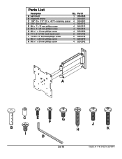
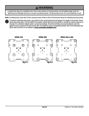
Parts List Description Qty. Part # A wall mount 1 095-0345 B Alligator® anchor 2 590-0097 C .198" ID x .313" OD x .437" H retaining spacer 4 590-5003 D 3/16" allen wrench 1 560-9713 E M4 x .7 x 12 mm phillips ...
Parts List Description Qty. Part # A wall mount 1 095-0345 B Alligator® anchor 2 590-0097 C .198" ID x .313" OD x .437" H retaining spacer 4 590-5003 D 3/16" allen wrench 1 560-9713 E M4 x .7 x 12 mm phillips ...
Installation Instructions
Page 4
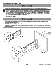
... two 5/32" (4 mm) dia. Skip to step 2 on page 6. WARNING • Tighten screws so that wall plate is highly recommended. The use of the stud. Attach wall mount (A) to wall using two #14 x 2.5" flat head wood screws (H) as template to mark center of 10 ISSUED: 01-17-... 1.1. holes 2.5" (65 mm) deep. Use wall plate as shown in figure 1.2. Installation to Wood Stud Wall WARNING • Make sure that the wall will safely support the combined load of the wood stud used in mounting this product. CORD COVER fig. 1.1 A WOOD STUD WALL H A fig. 1.2 4 of holes along ...
... two 5/32" (4 mm) dia. Skip to step 2 on page 6. WARNING • Tighten screws so that wall plate is highly recommended. The use of the stud. Attach wall mount (A) to wall using two #14 x 2.5" flat head wood screws (H) as template to mark center of 10 ISSUED: 01-17-... 1.1. holes 2.5" (65 mm) deep. Use wall plate as shown in figure 1.2. Installation to Wood Stud Wall WARNING • Make sure that the wall will safely support the combined load of the wood stud used in mounting this product. CORD COVER fig. 1.1 A WOOD STUD WALL H A fig. 1.2 4 of holes along ...
Installation Instructions
Page 5
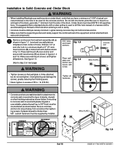
... all fasteners. Drill two 1/4" (6 mm) dia. Make sure wall mount is firmly attached, but do not pull away from concrete when tightening screws. fig. 1.4 concrete wall B WALL PLATE H B • Tighten screws so that wall plate is level, and tighten all attached hardware and components. 1... of 80 in a solid part of the block, generally 1" minimum from wall arm assembly (A) as shown in figures 1.4 and 1.6. Installation to Solid Concrete and Cinder Block WARNING • When installing Westinghouse wall mounts on cinder block, verify that you have a minimum of 1-3/8" of actual ...
... all fasteners. Drill two 1/4" (6 mm) dia. Make sure wall mount is firmly attached, but do not pull away from concrete when tightening screws. fig. 1.4 concrete wall B WALL PLATE H B • Tighten screws so that wall plate is level, and tighten all attached hardware and components. 1... of 80 in a solid part of the block, generally 1" minimum from wall arm assembly (A) as shown in figures 1.4 and 1.6. Installation to Solid Concrete and Cinder Block WARNING • When installing Westinghouse wall mounts on cinder block, verify that you have a minimum of 1-3/8" of actual ...
Installation Instructions
Page 6
... security screws. 2 To prevent scratching the screen, set a cloth on out website at www.westinghousedigital.com. For additional screen compatibility please refer to the Westinghouse Décor wall mount list on a flat, level surface that all holes are properly aligned, and then tighten screws using security allen wrench (D). Contact customer care for security...
... security screws. 2 To prevent scratching the screen, set a cloth on out website at www.westinghousedigital.com. For additional screen compatibility please refer to the Westinghouse Décor wall mount list on a flat, level surface that all holes are properly aligned, and then tighten screws using security allen wrench (D). Contact customer care for security...
Installation Instructions
Page 8
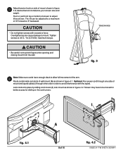
... to avoid interference with excessive force. Tighten screws to 40 in order to adjust tilt as shown. CAUTION • Be careful not to a maximum of mount and signal cable(s) through other side in . • lb (4.5 N.M.) maximum torque. TENSION KNOB fig. 3 Note: Make sure cords have to be adjusted to .... Screen may have enough slack to balance your screen size and weight. Overtightening can be moved for better access for sliding on side of wall mount (A) as shown in figure 3 to desired tension to allow full movement of the arm. 4 Route cords inside arm slots of...
... to avoid interference with excessive force. Tighten screws to 40 in order to adjust tilt as shown. CAUTION • Be careful not to a maximum of mount and signal cable(s) through other side in . • lb (4.5 N.M.) maximum torque. TENSION KNOB fig. 3 Note: Make sure cords have to be adjusted to .... Screen may have enough slack to balance your screen size and weight. Overtightening can be moved for better access for sliding on side of wall mount (A) as shown in figure 3 to desired tension to allow full movement of the arm. 4 Route cords inside arm slots of...