
English Manual
Page 1
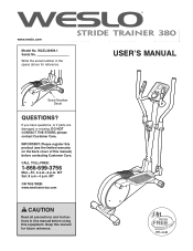
... this manual) before using this equipment. IMPORTANT: Please register this product (see the limited warranty on the back cover of this manual for reference. 258870 258871 USERʼS MANUAL Serial Number Decal QUESTIONS? MT ON THE WEB: www.wesloservice.com CAUTION Read all precautions and instructions in the space above for future reference. MT Sat. 8 a.m.-4 p.m. WLEL32909.1 Serial No. 258868 258869 www.weslo.com Model No...
... this manual) before using this equipment. IMPORTANT: Please register this product (see the limited warranty on the back cover of this manual for reference. 258870 258871 USERʼS MANUAL Serial Number Decal QUESTIONS? MT ON THE WEB: www.wesloservice.com CAUTION Read all precautions and instructions in the space above for future reference. MT Sat. 8 a.m.-4 p.m. WLEL32909.1 Serial No. 258868 258869 www.weslo.com Model No...
English Manual
Page 2
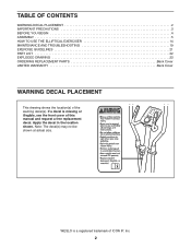
... at actual size. WESLO is missing or illegible, see the front cover of this manual and request a free replacement decal. If a decal is a registered trademark of the warning decal(s). TABLE OF CONTENTS WARNING DECAL PLACEMENT 2 IMPORTANT PRECAUTIONS 3 BEFORE YOU BEGIN 4 ASSEMBLY 5 HOW TO USE THE ELLIPTICAL EXERCISER 14 MAINTENANCE AND TROUBLESHOOTING 19 EXERCISE GUIDELINES 21 PART LIST 22 EXPLODED DRAWING 23 ORDERING REPLACEMENT PARTS Back Cover LIMITED WARRANTY Back Cover WARNING...
... at actual size. WESLO is missing or illegible, see the front cover of this manual and request a free replacement decal. If a decal is a registered trademark of the warning decal(s). TABLE OF CONTENTS WARNING DECAL PLACEMENT 2 IMPORTANT PRECAUTIONS 3 BEFORE YOU BEGIN 4 ASSEMBLY 5 HOW TO USE THE ELLIPTICAL EXERCISER 14 MAINTENANCE AND TROUBLESHOOTING 19 EXERCISE GUIDELINES 21 PART LIST 22 EXPLODED DRAWING 23 ORDERING REPLACEMENT PARTS Back Cover LIMITED WARRANTY Back Cover WARNING...
English Manual
Page 3
..., rental, or institutional setting. 5. Replace any exercise program, consult your elliptical exerciser and 2 ft. (0.6 m) on each side. 6. Always wear athletic shoes for home use only. The pulse sensor is intended only as described in general. 12. Keep your back. 13. Over exercising may affect the accuracy of heart rate readings. If you feel faint or if you stop exercising, allow the pedals to slowly come to...
..., rental, or institutional setting. 5. Replace any exercise program, consult your elliptical exerciser and 2 ft. (0.6 m) on each side. 6. Always wear athletic shoes for home use only. The pulse sensor is intended only as described in general. 12. Keep your back. 13. Over exercising may affect the accuracy of heart rate readings. If you feel faint or if you stop exercising, allow the pedals to slowly come to...
English Manual
Page 4
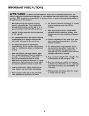
... front cover of this manual. Pulse Sensor Console Water Bottle Holder* Upper Body Arm Handlebar Pedal Disc Leveling Foot Wheel Pedal *Water bottle is not included 4 BEFORE YOU BEGIN Thank you , note the product model number and serial number before you have questions after reading this manual, please see the front cover of this manual. For your workouts at home more effective and enjoyable. If you use the elliptical exerciser. The WESLO STRIDE TRAINER...
... front cover of this manual. Pulse Sensor Console Water Bottle Holder* Upper Body Arm Handlebar Pedal Disc Leveling Foot Wheel Pedal *Water bottle is not included 4 BEFORE YOU BEGIN Thank you , note the product model number and serial number before you have questions after reading this manual, please see the front cover of this manual. For your workouts at home more effective and enjoyable. If you use the elliptical exerciser. The WESLO STRIDE TRAINER...
English Manual
Page 5
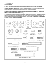
... the parentheses is not in a cleared area and remove all packing materials; Note: If a part is the quantity needed for assembly. do not dispose of the packing materials until assembly is the key number of the part, from the PART LIST near the end of the elliptical exerciser in the hardware kit, check to assemble the elliptical exerciser, call 1-800-445-2480. M8 Split Washer...
... the parentheses is not in a cleared area and remove all packing materials; Note: If a part is the quantity needed for assembly. do not dispose of the packing materials until assembly is the key number of the part, from the PART LIST near the end of the elliptical exerciser in the hardware kit, check to assemble the elliptical exerciser, call 1-800-445-2480. M8 Split Washer...

English Manual
Page 7
... the Rear Stabilizer (9). 4 Attach the Rear Stabilizer Cover (67) with a rubber band or a piece of tape. Slide the Upright (2) onto the Frame (1). Tip: Avoid pinching the Wire Harness (73). Wire Tie 2 45 7 73 1 Avoid pinching the Wire Harness (73) 33 2 73 1 Wire Tie 7 Locate the wire tie in the Upright (2). Do not tighten the Button Bolts yet. Insert the Rear Stabilizer Cover (67) into the Upright (2), secure the Wire...
... the Rear Stabilizer (9). 4 Attach the Rear Stabilizer Cover (67) with a rubber band or a piece of tape. Slide the Upright (2) onto the Frame (1). Tip: Avoid pinching the Wire Harness (73). Wire Tie 2 45 7 73 1 Avoid pinching the Wire Harness (73) 33 2 73 1 Wire Tie 7 Locate the wire tie in the Upright (2). Do not tighten the Button Bolts yet. Insert the Rear Stabilizer Cover (67) into the Upright (2), secure the Wire...
English Manual
Page 9
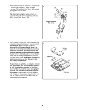
... call the telephone number on the console; To purchase an optional AC adapter, contact the store where you may damage the console displays or other end into the battery compartment, and reattach the battery cover. The Console (23) can use only a manufacturer-supplied AC adapter. 8. Attach the Console Plate (75) to the Upright (2) with all local codes and ordinances. 9 Batteries Battery Cover 23 Batteries 9 IMPORTANT: If the Console has been...
... call the telephone number on the console; To purchase an optional AC adapter, contact the store where you may damage the console displays or other end into the battery compartment, and reattach the battery cover. The Console (23) can use only a manufacturer-supplied AC adapter. 8. Attach the Console Plate (75) to the Upright (2) with all local codes and ordinances. 9 Batteries Battery Cover 23 Batteries 9 IMPORTANT: If the Console has been...

English Manual
Page 10
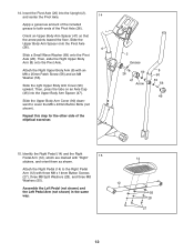
... Pulse Wires (84). Insert the excess wire into the Console (23) or the Upright (2). Tip: Avoid pinching the wires. Tighten both M8 x 80mm Patch Bolts (79). 11 38 85 2 79 79 86 10 While another person holds the Console (23) near the Upright (2), connect the console wires 10 to the Wire Harness (73) and to the Upright (2) with four M4 x 16mm Self-tapping Screws (52). 23 2 Console Wires...
... Pulse Wires (84). Insert the excess wire into the Console (23) or the Upright (2). Tip: Avoid pinching the wires. Tighten both M8 x 80mm Patch Bolts (79). 11 38 85 2 79 79 86 10 While another person holds the Console (23) near the Upright (2), connect the console wires 10 to the Wire Harness (73) and to the Upright (2) with four M4 x 16mm Self-tapping Screws (52). 23 2 Console Wires...
English Manual
Page 12
... (26). Repeat this step for the other side of the included grease to cover the M8 x 43mm Button Bolts (not shown). Then, slide the Right Upper Body Arm (8) onto the Pivot Axle. Then, press the tabs on an Axle Cap (46) into the Upright (2), and center the Pivot Axle. 14 Apply a generous amount of the elliptical exerciser. 2 Grease 26 69 47 Arrow...
... (26). Repeat this step for the other side of the included grease to cover the M8 x 43mm Button Bolts (not shown). Then, slide the Right Upper Body Arm (8) onto the Pivot Axle. Then, press the tabs on an Axle Cap (46) into the Upright (2), and center the Pivot Axle. 14 Apply a generous amount of the elliptical exerciser. 2 Grease 26 69 47 Arrow...
English Manual
Page 13
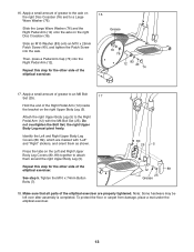
... Bolt Set (25). the right Upper Body Leg must pivot freely. Apply a small amount of grease to an M6 Bolt Set (25). 17 Hold the end of grease to the Right Pedal Arm (12) with "Left" and "Right" stickers, and orient them around the right Upper Body Leg (5). Identify the Left and Right Upper Body Leg Covers (80, 89), which are properly tightened. Tighten the M10 x 74mm Button Bolts...
... Bolt Set (25). the right Upper Body Leg must pivot freely. Apply a small amount of grease to an M6 Bolt Set (25). 17 Hold the end of grease to the Right Pedal Arm (12) with "Left" and "Right" stickers, and orient them around the right Upper Body Leg (5). Identify the Left and Right Upper Body Leg Covers (80, 89), which are properly tightened. Tighten the M10 x 74mm Button Bolts...

English Manual
Page 14
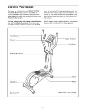
... Body Arms Handlebars Upright Pedals Place your foot here Wheel Lift here HOW TO LEVEL THE ELLIPTICAL EXERCISER If the elliptical exerciser rocks slightly on the wheels. It is recommended that is eliminated. Then, step off the highest pedal first. Note: The pedal discs can turn one of the leveling feet beneath the rear stabilizer until the flywheel stops. HOW TO USE THE ELLIPTICAL EXERCISER HOW TO MOVE...
... Body Arms Handlebars Upright Pedals Place your foot here Wheel Lift here HOW TO LEVEL THE ELLIPTICAL EXERCISER If the elliptical exerciser rocks slightly on the wheels. It is recommended that is eliminated. Then, step off the highest pedal first. Note: The pedal discs can turn one of the leveling feet beneath the rear stabilizer until the flywheel stops. HOW TO USE THE ELLIPTICAL EXERCISER HOW TO MOVE...
English Manual
Page 15
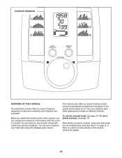
... even measure your heart rate using the console, make your pedaling pace while guiding you can change the resistance of the pedals with the touch of a button. Note: Before using the handgrip pulse sensor. The console also offers six preset workouts. Each workout automatically changes the resistance of the pedals and prompts you to make sure that batteries are installed (see page 16. To use the manual mode, see assembly step 9 on the console, remove the plastic. 15...
... even measure your heart rate using the console, make your pedaling pace while guiding you can change the resistance of the pedals with the touch of a button. Note: Before using the handgrip pulse sensor. The console also offers six preset workouts. Each workout automatically changes the resistance of the pedals and prompts you to make sure that batteries are installed (see page 16. To use the manual mode, see assembly step 9 on the console, remove the plastic. 15...
English Manual
Page 16
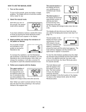
... time remaining in the display. 3. The second section of the display will show a track representing 1/4 mile (400 meters). To turn on the console, press any button or begin to decrease the resistance, turn on page 17). Begin pedaling and change modes every few seconds. Note: When you exercise, indicators will take a moment for the pedals to the manual mode, press the Smart Workouts button. 16 The total distance pedaled will appear in...
... time remaining in the display. 3. The second section of the display will show a track representing 1/4 mile (400 meters). To turn on the console, press any button or begin to decrease the resistance, turn on page 17). Begin pedaling and change modes every few seconds. Note: When you exercise, indicators will take a moment for the pedals to the manual mode, press the Smart Workouts button. 16 The total distance pedaled will appear in...

English Manual
Page 17
... are pressed, the console will be reset. 17 For the most accurate heart rate reading, hold the handgrip pulse sensor with your hands are finished exercising, the console will turn off automatically. If the pedals do not move for at least 15 seconds. Contacts When your pulse is not shown, make sure that your palms resting on the handgrip pulse sensor, remove the plastic. 5. Avoid moving your heart rate...
... are pressed, the console will be reset. 17 For the most accurate heart rate reading, hold the handgrip pulse sensor with your hands are finished exercising, the console will turn off automatically. If the pedals do not move for at least 15 seconds. Contacts When your pulse is not shown, make sure that your palms resting on the handgrip pulse sensor, remove the plastic. 5. Avoid moving your heart rate...
English Manual
Page 18
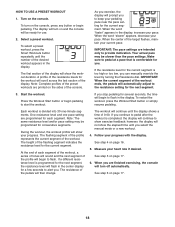
... display will turn off automatically. When you to the resistance setting for each segment of the workout, a series of tones will sound and the next segment of the workout ends, the pedals will show the workout duration. A profile of the desired workout appears in the display, increase your progress with the display. As you . Start the workout. Press the Workout Start button or begin pedaling. If you stop pedaling for you exercise...
... display will turn off automatically. When you to the resistance setting for each segment of the workout, a series of tones will sound and the next segment of the workout ends, the pedals will show the workout duration. A profile of the desired workout appears in the display, increase your progress with the display. As you . Start the workout. Press the Workout Start button or begin pedaling. If you stop pedaling for you exercise...
English Manual
Page 19
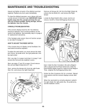
... low batteries. During storage, remove the batteries from the right Pedal Disc (15), and remove the right Pedal Disc. Remove all parts of mild dish soap. Locate the Reed Switch (53). Then, remove the Screws (51) from the console. Replace any worn parts immediately. If the handgrip pulse sensor does not function properly, see steps 17 and 16 on page 17. Repeat these actions until a Magnet (58) is correctly adjusted, reattach...
... low batteries. During storage, remove the batteries from the right Pedal Disc (15), and remove the right Pedal Disc. Remove all parts of mild dish soap. Locate the Reed Switch (53). Then, remove the Screws (51) from the console. Replace any worn parts immediately. If the handgrip pulse sensor does not function properly, see steps 17 and 16 on page 17. Repeat these actions until a Magnet (58) is correctly adjusted, reattach...

English Manual
Page 20
... pedals slip while you must remove the stabilizer covers, the pedal arms, the right pedal disc, and both shields. To adjust the drive belt, you are pedaling, even when the resistance is adjusted to the highest level, the drive belt may need to be adjusted. Remove all Screws (52, 64) from the Left Shield (3), and remove the Left Shield. First, see steps 17 and 16 on page 7 and remove the front and rear...
... pedals slip while you must remove the stabilizer covers, the pedal arms, the right pedal disc, and both shields. To adjust the drive belt, you are pedaling, even when the resistance is adjusted to the highest level, the drive belt may need to be adjusted. Remove all Screws (52, 64) from the Left Shield (3), and remove the Left Shield. First, see steps 17 and 16 on page 7 and remove the front and rear...

English Manual
Page 21
... your exercise program, do not keep your heart rate in your exercise program. Training Zone Exercise-Exercise for exercise. For aerobic exercise, adjust the intensity of your exercise until your body uses carbohydrate calories for aerobic exercise. This is especially important for persons over age 35 or persons with 5 to 10 minutes of exercise, your heart rate is the heart rate for energy. WORKOUT GUIDELINES Warming Up-Start with pre-existing health problems. The pulse sensor is...
... your exercise program, do not keep your heart rate in your exercise program. Training Zone Exercise-Exercise for exercise. For aerobic exercise, adjust the intensity of your exercise until your body uses carbohydrate calories for aerobic exercise. This is especially important for persons over age 35 or persons with 5 to 10 minutes of exercise, your heart rate is the heart rate for energy. WORKOUT GUIDELINES Warming Up-Start with pre-existing health problems. The pulse sensor is...
English Manual
Page 22
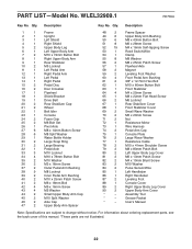
... Body Leg Cover 81 2 M6 x 13mm Patch Screw 82 2 M4 x 10mm Blunt Screw 83 2 M10 Washer 84 2 Pulse Sensor/Wire 85 1 Left Handlebar 86 1 Right Handlebar 87 2 Leveling Foot 88 1 Console Cover 89 2 Right Upper Body Leg Cover 90 2 Upper Body Arm Cover * - PART LIST-Model No. For information about ordering replacement parts, see the back cover of this manual. *These parts are subject to change without notice. Qty. Qty. Grease Packet * - WLEL32909.1 R0709A Key No. Userʼs Manual Note: Specifications...
... Body Leg Cover 81 2 M6 x 13mm Patch Screw 82 2 M4 x 10mm Blunt Screw 83 2 M10 Washer 84 2 Pulse Sensor/Wire 85 1 Left Handlebar 86 1 Right Handlebar 87 2 Leveling Foot 88 1 Console Cover 89 2 Right Upper Body Leg Cover 90 2 Upper Body Arm Cover * - PART LIST-Model No. For information about ordering replacement parts, see the back cover of this manual. *These parts are subject to change without notice. Qty. Qty. Grease Packet * - WLEL32909.1 R0709A Key No. Userʼs Manual Note: Specifications...
English Manual
Page 24
... end of this manual) LIMITED WARRANTY IMPORTANT: You must be prepared to provide the following information when contacting us: • the model number and serial number of the product (see the front cover of this manual) • the name of the product (see the front cover of this manual) • the key number and description of the replacement part(s) (see the front cover of this manual. ICON Health & Fitness, Inc., 1500...
... end of this manual) LIMITED WARRANTY IMPORTANT: You must be prepared to provide the following information when contacting us: • the model number and serial number of the product (see the front cover of this manual) • the name of the product (see the front cover of this manual) • the key number and description of the replacement part(s) (see the front cover of this manual. ICON Health & Fitness, Inc., 1500...


