
User Manual
Page 1
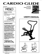
... Mon.-Fri., 6 a.m.-6 p.m. CAR/31Q GLIDE Patent Pending WESLO TARGET RESISTANCE TRAINER SrViF"ir''"*Of Ma05 Model No. If you . MST CAUTIO Retid4Ripoqaplfgo:0410::, . TO AVOID UNNECESSARY DELAYS, PLEASE CALL DIRECT TO OUR TOLL-FREE CUSTOMER HOT LINE. SOO titit litiA)04011$Mint.,:A0100 manual for reference. WLCR28060 Serial No. The trained technicians on our customer hot line will guaraniee...
... Mon.-Fri., 6 a.m.-6 p.m. CAR/31Q GLIDE Patent Pending WESLO TARGET RESISTANCE TRAINER SrViF"ir''"*Of Ma05 Model No. If you . MST CAUTIO Retid4Ripoqaplfgo:0410::, . TO AVOID UNNECESSARY DELAYS, PLEASE CALL DIRECT TO OUR TOLL-FREE CUSTOMER HOT LINE. SOO titit litiA)04011$Mint.,:A0100 manual for reference. WLCR28060 Serial No. The trained technicians on our customer hot line will guaraniee...

User Manual
Page 2
... preexisting health problems: a r :etruct tie befOre using ICON assumes no responsibility for personal Injury or property ma a .sustaine± by:or througkthe:ete of this or any exercise program, consult your back. i..n....e....d....f..a.....t.e. TABLE OF CONTENTS IMPORTANT PRECAUTIONS BEFORE YOU BEGIN ASSEMBLY HOW TO USE THE CARDIOGLIDE TR 2 MAINTENANCE AND TROUBLE-SHOOTING CONDITIONING GUIDELINES PART LIST P EXPLODED DRAWING ORDERING REPLACEMENT PARTS WARRANTY 2 3 4 5 8 9 10 11 Back Cover Back Cover...
... preexisting health problems: a r :etruct tie befOre using ICON assumes no responsibility for personal Injury or property ma a .sustaine± by:or througkthe:ete of this or any exercise program, consult your back. i..n....e....d....f..a.....t.e. TABLE OF CONTENTS IMPORTANT PRECAUTIONS BEFORE YOU BEGIN ASSEMBLY HOW TO USE THE CARDIOGLIDE TR 2 MAINTENANCE AND TROUBLE-SHOOTING CONDITIONING GUIDELINES PART LIST P EXPLODED DRAWING ORDERING REPLACEMENT PARTS WARRANTY 2 3 4 5 8 9 10 11 Back Cover Back Cover...
User Manual
Page 3
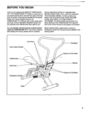
... both the upper and lower body for you , please note the product model number and serial number when calling. To help us assist you . Mountain Time (excluding holidays). Link Arms Quick Adjust Handle Padded Seat Seat Knob Resistance Cylinder Handlebar Rollers for Push Mode Monitor Rollers for selecting the WESLO® CARDIOGLIDE TR 2. The CARDIOGLIDE TR 2 offers a unique form of the decal). until 6 p.m. Service Department toll-free at the intensity...
... both the upper and lower body for you , please note the product model number and serial number when calling. To help us assist you . Mountain Time (excluding holidays). Link Arms Quick Adjust Handle Padded Seat Seat Knob Resistance Cylinder Handlebar Rollers for Push Mode Monitor Rollers for selecting the WESLO® CARDIOGLIDE TR 2. The CARDIOGLIDE TR 2 offers a unique form of the decal). until 6 p.m. Service Department toll-free at the intensity...
User Manual
Page 4
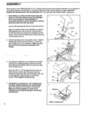
... of the batteries.are recommended. Note: Before you begin. Firmly tighten the Seat Knob. 4. Assembly requires the following tools: The included pedal tool Qs , and your own rubber mallet 1. ASSEMBLY Place all parts of the CARDIOGLIDE TR 2 in this step, make sure that the Handlebar 1 (2) is completed. Hold the Handle (20) and hook the Link Arms (4, 7) onto the 2 lower Rollers (33) on...
... of the batteries.are recommended. Note: Before you begin. Firmly tighten the Seat Knob. 4. Assembly requires the following tools: The included pedal tool Qs , and your own rubber mallet 1. ASSEMBLY Place all parts of the CARDIOGLIDE TR 2 in this step, make sure that the Handlebar 1 (2) is completed. Hold the Handle (20) and hook the Link Arms (4, 7) onto the 2 lower Rollers (33) on...
User Manual
Page 5
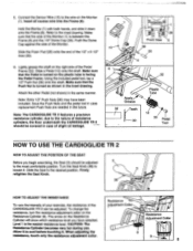
... shaft on the Monitor (1). When adjusting the resistance, touch only the resistance adjustment collar. Connect the Sensor Wire (15) to the inset drawing. Make sure that the Pedal is turned so the plastic tube is the easiest resistance level. Attach the other Pedal (not shown) in the future. Save the Push Nuts and the pedal tool in case replacement Push Nuts are needed in the same...
... shaft on the Monitor (1). When adjusting the resistance, touch only the resistance adjustment collar. Connect the Sensor Wire (15) to the inset drawing. Make sure that the Pedal is turned so the plastic tube is the easiest resistance level. Attach the other Pedal (not shown) in the future. Save the Push Nuts and the pedal tool in case replacement Push Nuts are needed in the same...

User Manual
Page 6
... the seat (see page 5). Do not arch your feet on the Handlebar. Return to the starting position. Repeat, moving with a smooth, continuous motion. CAUTION: Make sure that the Link Arms are securely connected to the starting position. To begin exercising, push the handlebar away with your arms while pushing the pedals away with your legs. For the best results, move through...
... the seat (see page 5). Do not arch your feet on the Handlebar. Return to the starting position. Repeat, moving with a smooth, continuous motion. CAUTION: Make sure that the Link Arms are securely connected to the starting position. To begin exercising, push the handlebar away with your arms while pushing the pedals away with your legs. For the best results, move through...
User Manual
Page 7
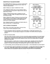
... pedals are not moved and the monitor buttons are described below: Speed-Displays your speed, in a repeating cycle. 1 Mode Indicators SPEED I onorb:onLi TIME DIST. Note: If you have monitor 2. 4. Note: If the resistance is near the highest or lowest setting, the actual number of Calories you stop exercising for ten seconds or longer, the time mode will appear for about four minutes, the power will then reset...
... pedals are not moved and the monitor buttons are described below: Speed-Displays your speed, in a repeating cycle. 1 Mode Indicators SPEED I onorb:onLi TIME DIST. Note: If you have monitor 2. 4. Note: If the resistance is near the highest or lowest setting, the actual number of Calories you stop exercising for ten seconds or longer, the time mode will appear for about four minutes, the power will then reset...
User Manual
Page 8
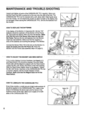
... with the Reed Switch. Keep liquids away 26 from the monitor. Loosen the #8 x 3/4" Screw (18) shown in the inset drawing. Insert all parts of light multi-purpose oil should be applied to the wire on the Monitor (1). Repeat until the Magnet is pushed all of the Sensor Wire does not slip into the Frame (6). Press the Monitor onto the Frame (see assembly step 5 on...
... with the Reed Switch. Keep liquids away 26 from the monitor. Loosen the #8 x 3/4" Screw (18) shown in the inset drawing. Insert all parts of light multi-purpose oil should be applied to the wire on the Monitor (1). Repeat until the Magnet is pushed all of the Sensor Wire does not slip into the Frame (6). Press the Monitor onto the Frame (see assembly step 5 on...
User Manual
Page 9
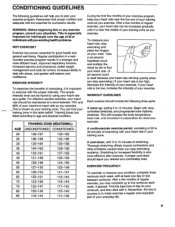
... weight management and body fat control, increased ability to exercise with the proper intensity. This is especially important for strenuous exercise. The proper intensity level can be found by ten to find your training zone in your training zone as you stop exercising.) If your training zone. This is too high, decrease the intensity of your training zone. To measure your heart rate, stop exercising...
... weight management and body fat control, increased ability to exercise with the proper intensity. This is especially important for strenuous exercise. The proper intensity level can be found by ten to find your training zone in your training zone as you stop exercising.) If your training zone. This is too high, decrease the intensity of your training zone. To measure your heart rate, stop exercising...
User Manual
Page 10
... 9 1 Resistance Cylinder 10 2 Pedal Frame Endcap 11 1 1 1/2" x 2" Endcap 12 2 Pedal 13 2 Link Arm Bushing 14 1 Bumper 15 1 Reed Switch/Sensor Wire 16 2 #8 x 1/2" Screw 17 1 1/2" x 5/8" Bumper 18 1 #8 x 3/4" Screw 19 1 Center Link Ann 20 1 Handle 21 1 3/8" x 10 3/8" Pivot Axle 22 1 1/2" x 3 1/4" Axle 23 2 1/2" Cylinder Bushing Set 24 2 .92.6" ABS Spacer 25 2 3/8" Bushing OR 1 Fa= Pad Key No. See the back cover of this manual for information about ordering replacement parts. 10...
... 9 1 Resistance Cylinder 10 2 Pedal Frame Endcap 11 1 1 1/2" x 2" Endcap 12 2 Pedal 13 2 Link Arm Bushing 14 1 Bumper 15 1 Reed Switch/Sensor Wire 16 2 #8 x 1/2" Screw 17 1 1/2" x 5/8" Bumper 18 1 #8 x 3/4" Screw 19 1 Center Link Ann 20 1 Handle 21 1 3/8" x 10 3/8" Pivot Axle 22 1 1/2" x 3 1/4" Axle 23 2 1/2" Cylinder Bushing Set 24 2 .92.6" ABS Spacer 25 2 3/8" Bushing OR 1 Fa= Pad Key No. See the back cover of this manual for information about ordering replacement parts. 10...
User Manual
Page 11
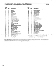
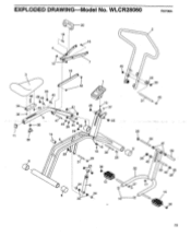
WLCR28060 R0796A 20 2 16 4 • • 13 7 45 19 3 9 42 29 4 29 43 40 Offd 34 35 38 25 5 47 8 43 29 44 29 29-0 • 14 6 15 37 e • V-25 f 15 • 29 18 28 29 29 8 31 3 30 12 2 9 8 24 23 10 33 30 O' 45 21 29 39 8 29 40 32 41 26 22 40)49p 29 27 17 12 iU 30 11 EXPLODED DRAWING Model No.
WLCR28060 R0796A 20 2 16 4 • • 13 7 45 19 3 9 42 29 4 29 43 40 Offd 34 35 38 25 5 47 8 43 29 44 29 29-0 • 14 6 15 37 e • V-25 f 15 • 29 18 28 29 29 8 31 3 30 12 2 9 8 24 23 10 33 30 O' 45 21 29 39 8 29 40 32 41 26 22 40)49p 29 27 17 12 iU 30 11 EXPLODED DRAWING Model No.
User Manual
Page 12
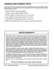
... give the following information: • The MODEL NUMBER of the product. (WLCR28060) • The NAME of the product. (WESLO® CARDIOGLIDE TR 2) • The SERIAL NUMBER of the product. (See the front cover of this manual.) • The KEY NUMBER of the part(s) needed. (See page 10 of this manual.) • The DESCRIPTION of the part(s) needed. (See page 10 of its authorized service centers. All...
... give the following information: • The MODEL NUMBER of the product. (WLCR28060) • The NAME of the product. (WESLO® CARDIOGLIDE TR 2) • The SERIAL NUMBER of the product. (See the front cover of this manual.) • The KEY NUMBER of the part(s) needed. (See page 10 of this manual.) • The DESCRIPTION of the part(s) needed. (See page 10 of its authorized service centers. All...


