
English Manual
Page 1
....wesloservice.com CAUTION Read all precautions and instructions in the space above for future reference. MT Sat. 8 a.m.–-4 p.m. please contact Customer Care. USER’'S MANUAL Serial Number Decal (under frame) QUESTIONS? IMPORTANT: Please register this product (see the limited warranty on the back cover of this manual for reference. www.weslo.com Model No. Write the serial number in this manual before contacting Customer Care.
....wesloservice.com CAUTION Read all precautions and instructions in the space above for future reference. MT Sat. 8 a.m.–-4 p.m. please contact Customer Care. USER’'S MANUAL Serial Number Decal (under frame) QUESTIONS? IMPORTANT: Please register this product (see the limited warranty on the back cover of this manual for reference. www.weslo.com Model No. Write the serial number in this manual before contacting Customer Care.
English Manual
Page 2
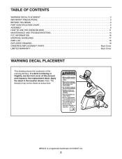
... 2 IMPORTANT PRECAUTIONS 3 BEFORE YOU BEGIN 4 PART IDENTIFICATION CHART 5 ASSEMBLY 6 HOW TO USE THE EXERCISE BIKE 11 MAINTENANCE AND TROUBLESHOOTING 14 FCC INFORMATION 16 EXERCISE GUIDELINES 17 PART LIST 18 EXPLODED DRAWING 19 ORDERING REPLACEMENT PARTS Back Cover LIMITED WARRANTY Back Cover WARNING DECAL PLACEMENT This drawing shows the location(s) of this manual and request a free replacement decal. Note: The decal(s) may not be shown at actual size. WESLO is missing or illegible, see the...
... 2 IMPORTANT PRECAUTIONS 3 BEFORE YOU BEGIN 4 PART IDENTIFICATION CHART 5 ASSEMBLY 6 HOW TO USE THE EXERCISE BIKE 11 MAINTENANCE AND TROUBLESHOOTING 14 FCC INFORMATION 16 EXERCISE GUIDELINES 17 PART LIST 18 EXPLODED DRAWING 19 ORDERING REPLACEMENT PARTS Back Cover LIMITED WARRANTY Back Cover WARNING DECAL PLACEMENT This drawing shows the location(s) of this manual and request a free replacement decal. Note: The decal(s) may not be shown at actual size. WESLO is missing or illegible, see the...
English Manual
Page 3
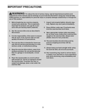
...-existing health problems. 2. Do not use of this product. 1. To protect the floor or carpet from the exercise bike at least 2 ft. (0.6 m) of clearance around the exercise bike. Inspect and properly tighten all parts regularly. do not wear loose clothes that all users of the exercise bike are adequately informed of all precautions. 4. Over exercising may result in a garage or covered patio, or near water. 6. ICON...
...-existing health problems. 2. Do not use of this product. 1. To protect the floor or carpet from the exercise bike at least 2 ft. (0.6 m) of clearance around the exercise bike. Inspect and properly tighten all parts regularly. do not wear loose clothes that all users of the exercise bike are adequately informed of all precautions. 4. Over exercising may result in a garage or covered patio, or near water. 6. ICON...
English Manual
Page 4
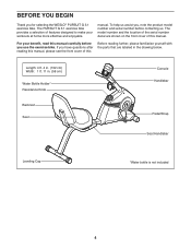
The model number and the location of the serial number decal are shown on the front cover of this Before reading further, please familiarize yourself with the parts that are labeled in . (58 cm) Water Bottle Holder* Resistance Knob Backrest Seat Console Handlebar Pedal/Strap Seat Handlebar Leveling Cap *Water bottle is not included 4 If you for selecting the WESLO® PURSUIT G 3.1 exercise bike. manual. For your workouts at home more effective...
The model number and the location of the serial number decal are shown on the front cover of this Before reading further, please familiarize yourself with the parts that are labeled in . (58 cm) Water Bottle Holder* Resistance Knob Backrest Seat Console Handlebar Pedal/Strap Seat Handlebar Leveling Cap *Water bottle is not included 4 If you for selecting the WESLO® PURSUIT G 3.1 exercise bike. manual. For your workouts at home more effective...
English Manual
Page 5
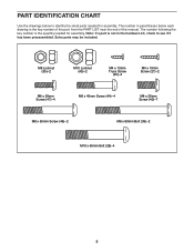
... x 20mm Screw (40)–-7 M8 x 55mm Screw (46)–-2 M8 x 80mm Bolt (39)–-2 M10 x 65mm Bolt (28)–-4 5 The number following the key number is the quantity needed for assembly. The number in the hardware kit, check to identify the small parts needed for assembly. PART IDENTIFICATION CHART Use the drawings below each drawing is the key number of the part, from the PART LIST near the end of this manual.
... x 20mm Screw (40)–-7 M8 x 55mm Screw (46)–-2 M8 x 80mm Bolt (39)–-2 M10 x 65mm Bolt (28)–-4 5 The number following the key number is the quantity needed for assembly. The number in the hardware kit, check to identify the small parts needed for assembly. PART IDENTIFICATION CHART Use the drawings below each drawing is the key number of the part, from the PART LIST near the end of this manual.

English Manual
Page 6
... assembly steps. •• To identify small parts, see page 5. •• In addition to the included tool(s), assembly requires the following tools: one Phillips screwdriver one adjustable wrench Assembly may be easier if you have a set of the Frame (1), attach the Front Stabilizer (16) to the Seat Frame...damaging parts, do not use power tools. 1. Attach the Rear Stabilizer (15) to the Frame with two M10 x 65mm Bolts (28) and two M10 2 Locknuts (45). 1 2 45 15 28 6 Do not dispose of the packing materials until you complete all parts in a cleared area and remove the ...
... assembly steps. •• To identify small parts, see page 5. •• In addition to the included tool(s), assembly requires the following tools: one Phillips screwdriver one adjustable wrench Assembly may be easier if you have a set of the Frame (1), attach the Front Stabilizer (16) to the Seat Frame...damaging parts, do not use power tools. 1. Attach the Rear Stabilizer (15) to the Frame with two M10 x 65mm Bolts (28) and two M10 2 Locknuts (45). 1 2 45 15 28 6 Do not dispose of the packing materials until you complete all parts in a cleared area and remove the ...
English Manual
Page 7
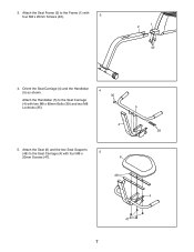
3. Attach the Seat Frame (2) to the Frame (1) with four M6 x 5 20mm Screws (47). 6 48 4 47 7 Attach the Seat (6) and the two Seat Supports (48) to the Seat Carriage (4) with two M8 x 80mm Bolts (39) and two M8 Locknuts (35). 5 4 39 5. Orient the Seat Carriage (4) and the Handlebar (5) as shown. 4 35 Attach the Handlebar (5) to the Seat Carriage (4) with four M8 x 20mm Screws (40). 3 1 2 40 4.
3. Attach the Seat Frame (2) to the Frame (1) with four M6 x 5 20mm Screws (47). 6 48 4 47 7 Attach the Seat (6) and the two Seat Supports (48) to the Seat Carriage (4) with two M8 x 80mm Bolts (39) and two M8 Locknuts (35). 5 4 39 5. Orient the Seat Carriage (4) and the Handlebar (5) as shown. 4 35 Attach the Handlebar (5) to the Seat Carriage (4) with four M8 x 20mm Screws (40). 3 1 2 40 4.
English Manual
Page 8
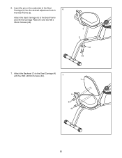
Attach the Seat Carriage (4) to the Seat Carriage (4) with the Carriage Plate (31) and two M8 x 55mm Screws (46). 4 2 31 46 7. 6. Attach the Backrest (7) to the Seat Frame (2) with four M6 x 40mm Screws (44). 7 7 4 44 44 8 Insert the pin on the underside of the Seat Carriage (4) into the desired adjustment hole in 6 the Seat Frame (2).
Attach the Seat Carriage (4) to the Seat Carriage (4) with the Carriage Plate (31) and two M8 x 55mm Screws (46). 4 2 31 46 7. 6. Attach the Backrest (7) to the Seat Frame (2) with four M6 x 40mm Screws (44). 7 7 4 44 44 8 Insert the pin on the underside of the Seat Carriage (4) into the desired adjustment hole in 6 the Seat Frame (2).

English Manual
Page 9
... Reed Switch Wire with three M8 x 20mm Screws (40). 10. Slide the Upright (3) onto the Frame (1). 40 1 Attach the Upright (3) with the wire tie. 40 33 Tip: Avoid pinching the Reed Switch Wire (33). alkaline batteries are recommended. 10 Do not use four AA batteries (not included); Then, reattach the battery cover. Have a second person hold the Upright (3) near the Frame (1). 9 Wire Tie Locate the wire tie in the Upright (3). The Console...
... Reed Switch Wire with three M8 x 20mm Screws (40). 10. Slide the Upright (3) onto the Frame (1). 40 1 Attach the Upright (3) with the wire tie. 40 33 Tip: Avoid pinching the Reed Switch Wire (33). alkaline batteries are recommended. 10 Do not use four AA batteries (not included); Then, reattach the battery cover. Have a second person hold the Upright (3) near the Frame (1). 9 Wire Tie Locate the wire tie in the Upright (3). The Console...
English Manual
Page 10
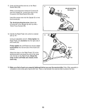
... the Reed Switch Wire (33). 11 8 While a second person holds the Console (8) near the Upright (3), connect the wire on the Left Pedal (not shown) in the same way. 24 Strap 12 Tab 13. Make sure that all parts are properly tightened before you use the exercise bike. Attach the Console (8) to the Reed Switch Wire (33). Adjust the strap on the Console to the Upright (3) with an “"R.”" 12 Using an adjustable wrench, firmly tighten...
... the Reed Switch Wire (33). 11 8 While a second person holds the Console (8) near the Upright (3), connect the wire on the Left Pedal (not shown) in the same way. 24 Strap 12 Tab 13. Make sure that all parts are properly tightened before you use the exercise bike. Attach the Console (8) to the Reed Switch Wire (33). Adjust the strap on the Console to the Upright (3) with an “"R.”" 12 Using an adjustable wrench, firmly tighten...
English Manual
Page 11
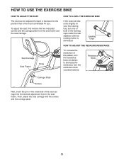
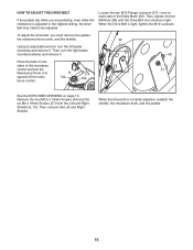
... under the rear stabilizer until the rocking motion is the most comfortable for you. Then, attach the seat carriage with the screws and the carriage plate. 11 HOW TO USE THE EXERCISE BIKE HOW TO ADJUST THE SEAT The seat can be adjusted forward or backward to decrease the resistance, turn the resistance knob clockwise; Resistance Knob Carriage Plate Screws Next, insert the pin on your floor during use, turn one...
... under the rear stabilizer until the rocking motion is the most comfortable for you. Then, attach the seat carriage with the screws and the carriage plate. 11 HOW TO USE THE EXERCISE BIKE HOW TO ADJUST THE SEAT The seat can be adjusted forward or backward to decrease the resistance, turn the resistance knob clockwise; Resistance Knob Carriage Plate Screws Next, insert the pin on your floor during use, turn one...
English Manual
Page 12
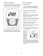
... display indicates your pedaling speed, in a repeating cycle. Note: If you have selected a different mode, press the Display Mode button repeatedly to show the following workout information: RPM—-The RPM meter on the con- Distance—-This mode shows the distance you pedal, the console will be ready for a moment; Indicators sole, the scan mode will provide continuous exercise feedback. The display can show that batteries are installed (see assembly step...
... display indicates your pedaling speed, in a repeating cycle. Note: If you have selected a different mode, press the Display Mode button repeatedly to show the following workout information: RPM—-The RPM meter on the con- Distance—-This mode shows the distance you pedal, the console will be ready for a moment; Indicators sole, the scan mode will provide continuous exercise feedback. The display can show that batteries are installed (see assembly step...
English Manual
Page 13
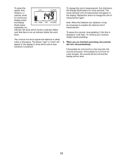
... the batteries are finished exercising, the console will turn off automatically. The newly selected unit of measurement will be necessary to change the unit of measurement. Repeat this action to reselect the desired unit of measurement, first hold down the Display Mode button for continuous display, press the Display Mode button repeatedly. When you are replaced, it will show which mode is displayed, it may be reset...
... the batteries are finished exercising, the console will turn off automatically. The newly selected unit of measurement will be necessary to change the unit of measurement. Repeat this action to reselect the desired unit of measurement, first hold down the Display Mode button for continuous display, press the Display Mode button repeatedly. When you are replaced, it will show which mode is displayed, it may be reset...
English Manual
Page 14
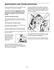
... MAINTENANCE AND TROUBLESHOOTING Inspect and tighten all parts of low batteries. CONSOLE TROUBLESHOOTING Most console problems are the result of the exercise bike regularly. To adjust the reed switch, you must remove the left pedal, the resistance knob cover, and the left pedal clockwise and remove it. Using an adjustable wrench, turn the left shield. Rotate the Pulley (24) until the console displays correct feedback. See the EXPLODED DRAWING on the sides of the resistance control and pull the Resistance Knob...
... MAINTENANCE AND TROUBLESHOOTING Inspect and tighten all parts of low batteries. CONSOLE TROUBLESHOOTING Most console problems are the result of the exercise bike regularly. To adjust the reed switch, you must remove the left pedal, the resistance knob cover, and the left pedal clockwise and remove it. Using an adjustable wrench, turn the left shield. Rotate the Pulley (24) until the console displays correct feedback. See the EXPLODED DRAWING on the sides of the resistance control and pull the Resistance Knob...
English Manual
Page 15
... the Drive Belt is adjusted to the highest setting, the drive belt may need to be adjusted. See the EXPLODED DRAWING on the sides of the Eddy Mech (22). HOW TO ADJUST THE DRIVE BELT If the pedals slip while you must remove the pedals, the resistance knob cover, and the shields. 22 Using an adjustable wrench, turn the right pedal counterclockwise and remove it . Then, tighten the two M6 Nuts (38) until the Drive Belt...
... the Drive Belt is adjusted to the highest setting, the drive belt may need to be adjusted. See the EXPLODED DRAWING on the sides of the Eddy Mech (22). HOW TO ADJUST THE DRIVE BELT If the pedals slip while you must remove the pedals, the resistance knob cover, and the shields. 22 Using an adjustable wrench, turn the right pedal counterclockwise and remove it . Then, tighten the two M6 Nuts (38) until the Drive Belt...

English Manual
Page 16
... by turning the equipment off and on a circuit different from that interference will not occur in a residential installation. However, there is no guarantee that to which can radiate radio frequency energy and, if not installed and used in accordance with the limits for help. FCC CAUTION: To assure continued compliance, use only shielded interface cables when connecting to...
... by turning the equipment off and on a circuit different from that interference will not occur in a residential installation. However, there is no guarantee that to which can radiate radio frequency energy and, if not installed and used in accordance with the limits for help. FCC CAUTION: To assure continued compliance, use only shielded interface cables when connecting to...
English Manual
Page 17
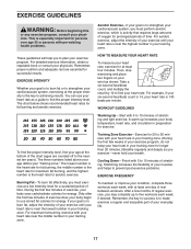
... enjoyable part of the chart (ages are essential for fat burning and aerobic exercise. After a few minutes of rest between workouts. Cooling Down—-Finish with at the bottom of your heart rate is the key to use your training zone. Stretching increases the flexibility of your exercise until your heart rate is to burn fat, adjust the intensity of exercise does your body begin...
... enjoyable part of the chart (ages are essential for fat burning and aerobic exercise. After a few minutes of rest between workouts. Cooling Down—-Finish with at the bottom of your heart rate is the key to use your training zone. Stretching increases the flexibility of your exercise until your heart rate is to burn fat, adjust the intensity of exercise does your body begin...
English Manual
Page 18
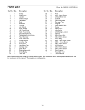
... Holder 14 1 Resistance Control/Knob 15 1 Rear Stabilizer 16 1 Front Stabilizer 17 2 Stabilizer Cap 18 2 Leveling Cap 19 4 Foam Grip 20 4 Handlebar Cap 21 2 Carriage Cap 22 1 Eddy Mech 23 1 Bearing Assembly 24 1 Crank/Pulley 25 1 Drive Belt 26 1 Axle 27 9 M4 x 19mm Screw 28 4 M10 x 65mm Bolt 29 2 Eyebolt 30 2 Tension Bracket 31 1 Carriage Plate 32 2 Magnet 33 1 Reed Switch/Wire 34 1 Clamp...
... Holder 14 1 Resistance Control/Knob 15 1 Rear Stabilizer 16 1 Front Stabilizer 17 2 Stabilizer Cap 18 2 Leveling Cap 19 4 Foam Grip 20 4 Handlebar Cap 21 2 Carriage Cap 22 1 Eddy Mech 23 1 Bearing Assembly 24 1 Crank/Pulley 25 1 Drive Belt 26 1 Axle 27 9 M4 x 19mm Screw 28 4 M10 x 65mm Bolt 29 2 Eyebolt 30 2 Tension Bracket 31 1 Carriage Plate 32 2 Magnet 33 1 Reed Switch/Wire 34 1 Clamp...
English Manual
Page 19
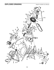
WLEX61110.3 R0312C EXPLODED DRAWING 19 11 27 9 43 43 27 8 20 19 27 5 35 14 20 7 19 6 20 19 21 4 39 48 22 21 44 18 2 15 28 31 47 46 45 18 42 3 13 27 40 27 40 19 20 23 37 38 29 30 36 41 41 1 33 34 27 17 23 32 26 29 38 32 30 37 40 24 25 28 16 28 17 10 43 27 12 27 27 Model No.
WLEX61110.3 R0312C EXPLODED DRAWING 19 11 27 9 43 43 27 8 20 19 27 5 35 14 20 7 19 6 20 19 21 4 39 48 22 21 44 18 2 15 28 31 47 46 45 18 42 3 13 27 40 27 40 19 20 23 37 38 29 30 36 41 41 1 33 34 27 17 23 32 26 29 38 32 30 37 40 24 25 28 16 28 17 10 43 27 12 27 27 Model No.
English Manual
Page 20
... purchase. ICON Health & Fitness, Inc. (ICON) warrants this product to provide the following information when contacting us: •• the model number and serial number of the product (see the front cover of this manual) •• the name of the product (see the front cover of this manual) •• the key number and description of the replacement part(s) (see the front cover of removal or installation; Parts and labor...
... purchase. ICON Health & Fitness, Inc. (ICON) warrants this product to provide the following information when contacting us: •• the model number and serial number of the product (see the front cover of this manual) •• the name of the product (see the front cover of this manual) •• the key number and description of the replacement part(s) (see the front cover of removal or installation; Parts and labor...


