
German Manual
Page 15
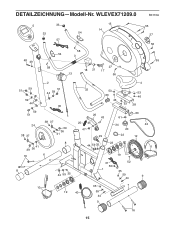
WLEVEX71209.0 R0110A 5 33 33 57 15 14 54 48 49 58 54 3 58 18 21 27 17 13 56 55 27 56 55 51 59 59 44 59 51 24 38 37 2 51 44 59 30 38 37 39 36 41 4 32 53 53 60 46 46 53 28 26 43 25 45 47 29 60 61 34 42 20 22 12 39 36 41 16 6 8 8 44 59 35 44 59 35 23 31 50 1 19 52 35 59 44 11 9 10 35 7 19 40 59 44 9 16 15 DETAILZEICHNUNG-Modell-Nr.
WLEVEX71209.0 R0110A 5 33 33 57 15 14 54 48 49 58 54 3 58 18 21 27 17 13 56 55 27 56 55 51 59 59 44 59 51 24 38 37 2 51 44 59 30 38 37 39 36 41 4 32 53 53 60 46 46 53 28 26 43 25 45 47 29 60 61 34 42 20 22 12 39 36 41 16 6 8 8 44 59 35 44 59 35 23 31 50 1 19 52 35 59 44 11 9 10 35 7 19 40 59 44 9 16 15 DETAILZEICHNUNG-Modell-Nr.
Uk Manual
Page 1
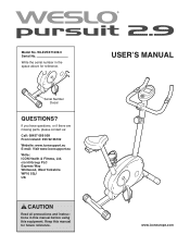
If you have questions, or if there are missing parts, please contact us: Call: 08457 089 009 From Ireland: 053 92 36102 Website: www.iconsupport.eu E-mail: Visit www.iconsupport.eu Write: ICON Health & Fitness, Ltd. USERʼS MANUAL www.iconeurope.com WLEVEX71209.0 Serial No. Serial Number Decal QUESTIONS? Keep this equipment. c/o HI Group PLC Express Way Whitwood, West Yorkshire WF10 5QJ UK CAUTION Read all precautions and instructions in the space above for future reference. Write the serial number in this manual before using this manual for reference. Model No.
If you have questions, or if there are missing parts, please contact us: Call: 08457 089 009 From Ireland: 053 92 36102 Website: www.iconsupport.eu E-mail: Visit www.iconsupport.eu Write: ICON Health & Fitness, Ltd. USERʼS MANUAL www.iconeurope.com WLEVEX71209.0 Serial No. Serial Number Decal QUESTIONS? Keep this equipment. c/o HI Group PLC Express Way Whitwood, West Yorkshire WF10 5QJ UK CAUTION Read all precautions and instructions in the space above for future reference. Write the serial number in this manual before using this manual for reference. Model No.
Uk Manual
Page 2
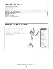
... location shown. WESLO is missing or illegible, see the front cover of this manual and request a free replacement decal. If a decal is a registered trademark of the warning decal(s). Note: The decal(s) may not be shown at actual size. TABLE OF CONTENTS WARNING DECAL PLACEMENT 2 IMPORTANT PRECAUTIONS 3 BEFORE YOU BEGIN 4 ASSEMBLY 5 HOW TO USE THE EXERCISE CYCLE 9 MAINTENANCE AND TROUBLESHOOTING 12 EXERCISE GUIDELINES 13 PART LIST...
... location shown. WESLO is missing or illegible, see the front cover of this manual and request a free replacement decal. If a decal is a registered trademark of the warning decal(s). Note: The decal(s) may not be shown at actual size. TABLE OF CONTENTS WARNING DECAL PLACEMENT 2 IMPORTANT PRECAUTIONS 3 BEFORE YOU BEGIN 4 ASSEMBLY 5 HOW TO USE THE EXERCISE CYCLE 9 MAINTENANCE AND TROUBLESHOOTING 12 EXERCISE GUIDELINES 13 PART LIST...
Uk Manual
Page 3
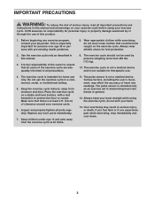
...Replace any exercise program, consult your back. 13. Keep children under age 12 and pets away from moisture and dust. The pulse sensor is not suitable for therapeutic use only. The pulse sensor is the responsibility of the owner to protect the floor or carpet. do not wear loose clothes that all users of the exercise cycle are adequately informed of heart rate readings. Use...and instructions in this manual and all parts regularly. Do not use of this manual. 3. Inspect and properly tighten all warnings on a stable and level surface, with pre-existing health problems. 8. ICON ...
...Replace any exercise program, consult your back. 13. Keep children under age 12 and pets away from moisture and dust. The pulse sensor is not suitable for therapeutic use only. The pulse sensor is the responsibility of the owner to protect the floor or carpet. do not wear loose clothes that all users of the exercise cycle are adequately informed of heart rate readings. Use...and instructions in this manual and all parts regularly. Do not use of this manual. 3. Inspect and properly tighten all warnings on a stable and level surface, with pre-existing health problems. 8. ICON ...
Uk Manual
Page 4
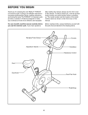
... the body. For your workouts at home more effective and enjoyable. To help us assist you, note the product model number and serial number before you have questions after reading this manual, please see the front cover of this manual. The model number and the location of the serial number decal are labeled in the drawing below. Handgrip Pulse Sensor Adjustment Handle Seat Seat Knob Console Handlebar Resistance Control Seat Post Knob Pedal/Strap 4 If you use the exercise cycle...
... the body. For your workouts at home more effective and enjoyable. To help us assist you, note the product model number and serial number before you have questions after reading this manual, please see the front cover of this manual. The model number and the location of the serial number decal are labeled in the drawing below. Handgrip Pulse Sensor Adjustment Handle Seat Seat Knob Console Handlebar Resistance Control Seat Post Knob Pedal/Strap 4 If you use the exercise cycle...
Uk Manual
Page 5
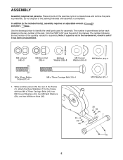
... rear of this manual. Note: If a part is the key number of the part, from the PART LIST near the end of the Frame (1), attach the Rear Stabilizer (7) to identify the small parts used for assembly. M8 Locknut (46)-3 M8 Acorn Nut (35)-4 M8 Split Washer (59)-8 M8 Curved Washer (44)-8 M8 Washer (53)-3 M8 x 20mm Button Screw (51)-4 M8 x 75mm Carriage Bolt (16)-4 1. Place all parts...
... rear of this manual. Note: If a part is the key number of the part, from the PART LIST near the end of the Frame (1), attach the Rear Stabilizer (7) to identify the small parts used for assembly. M8 Locknut (46)-3 M8 Acorn Nut (35)-4 M8 Split Washer (59)-8 M8 Curved Washer (44)-8 M8 Washer (53)-3 M8 x 20mm Button Screw (51)-4 M8 x 75mm Carriage Bolt (16)-4 1. Place all parts...
Uk Manual
Page 6
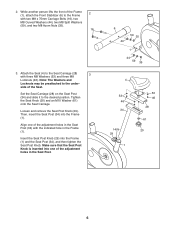
... (35). 16 3. Then, insert the Seat Post (34) into the Frame (1) and the Seat Post (34), and then tighten the Seat Post Knob. side of the Frame 2 (1), attach the Front Stabilizer (6) to the Seat Carriage (28) with the indicated hole in the Seat Post. 6 44 59 35 1 44 59... remove the Seat Post Knob (29). Insert the Seat Post Knob (29) into the Frame (1). Make sure that the Seat Post Knob is inserted into one of the adjustment holes in the Frame (1). Tighten the Seat Knob (20) and an M10 Washer (61) onto the Seat Carriage. Align one of the adjustment holes in the Seat...
... (35). 16 3. Then, insert the Seat Post (34) into the Frame (1) and the Seat Post (34), and then tighten the Seat Post Knob. side of the Frame 2 (1), attach the Front Stabilizer (6) to the Seat Carriage (28) with the indicated hole in the Seat Post. 6 44 59 35 1 44 59... remove the Seat Post Knob (29). Insert the Seat Post Knob (29) into the Frame (1). Make sure that the Seat Post Knob is inserted into one of the adjustment holes in the Frame (1). Tighten the Seat Knob (20) and an M10 Washer (61) onto the Seat Carriage. Align one of the adjustment holes in the Seat...
Uk Manual
Page 7
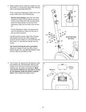
... from the top of the connector. Make sure that the batteries are recommended. Press the small cylinder on the Lower Cable (40) from the Console and insert two batteries into the battery compartment. The Console (5) requires two AA batteries; Remove the 5 battery cover from the side shown. Batteries Battery Cover 5 7 Attach the Upright (2) with four M8 x 20mm Button Screws (51), four M8 Split Washers (59), and four M8 Curved...
... from the top of the connector. Make sure that the batteries are recommended. Press the small cylinder on the Lower Cable (40) from the Console and insert two batteries into the battery compartment. The Console (5) requires two AA batteries; Remove the 5 battery cover from the side shown. Batteries Battery Cover 5 7 Attach the Upright (2) with four M8 x 20mm Button Screws (51), four M8 Split Washers (59), and four M8 Curved...
Uk Manual
Page 8
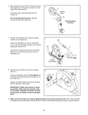
... all parts are properly tightened before you use the exercise cycle. Using an adjustable wrench, firmly tighten the Left Pedal counterclockwise into the right arm of the Crank. Tip: Avoid pinching the wires. Position the Handlebar (3) inside the hinged 7 bracket on the Upright (2). Identify the Left Pedal (10), which is completed, some extra parts may be kept tightened. 9. Note: After assembly is marked 8 with the Handlebar Cover...
... all parts are properly tightened before you use the exercise cycle. Using an adjustable wrench, firmly tighten the Left Pedal counterclockwise into the right arm of the Crank. Tip: Avoid pinching the wires. Position the Handlebar (3) inside the hinged 7 bracket on the Upright (2). Identify the Left Pedal (10), which is completed, some extra parts may be kept tightened. 9. Note: After assembly is marked 8 with the Handlebar Cover...
Uk Manual
Page 9
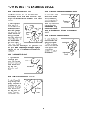
... the pedals, turn the control Resistance Control counterclockwise. IMPORTANT: Stop turning the control when turning becomes difficult, or damage may result. HOW TO ADJUST THE SEAT To adjust the seat, loosen the seat knob, slide the seat forward or backward to the desired position and then retighten the adjustment handle. Pivot the handlebar forward or backward to the desired position, and then tighten the seat knob. tance of the adjustment holes...
... the pedals, turn the control Resistance Control counterclockwise. IMPORTANT: Stop turning the control when turning becomes difficult, or damage may result. HOW TO ADJUST THE SEAT To adjust the seat, loosen the seat knob, slide the seat forward or backward to the desired position and then retighten the adjustment handle. Pivot the handlebar forward or backward to the desired position, and then tighten the seat knob. tance of the adjustment holes...
Uk Manual
Page 10
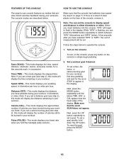
.... Next, press the MODE button repeatedly until the letters TMR, DST, or CAL appear near the lower edge of the console, remove it. Make sure that the console has batteries (see step 2), this mode will display the number of calories you set . Pulse (PULSE)-This mode displays your workout, in the display. To set a time goal (see assembly step 5 on the face of the display. When you have pedaled during your workout, first stop pedaling and wait...
.... Next, press the MODE button repeatedly until the letters TMR, DST, or CAL appear near the lower edge of the console, remove it. Make sure that the console has batteries (see step 2), this mode will display the number of calories you set . Pulse (PULSE)-This mode displays your workout, in the display. To set a time goal (see assembly step 5 on the face of the display. When you have pedaled during your workout, first stop pedaling and wait...
Uk Manual
Page 11
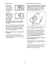
... display. For optimal performance, periodically clean the metal contacts using a soft cloth; Then, press the RESET button. 4. For the most accurate heart rate reading, continue to clean the contacts. 6. Place your heart rate, if desired. If the pedals do not move and the console buttons are sheets of these modes for several seconds when you have set a workout goal, a tone will turn off automatically to save the batteries...
... display. For optimal performance, periodically clean the metal contacts using a soft cloth; Then, press the RESET button. 4. For the most accurate heart rate reading, continue to clean the contacts. 6. Place your heart rate, if desired. If the pedals do not move and the console buttons are sheets of these modes for several seconds when you have set a workout goal, a tone will turn off automatically to save the batteries...

Uk Manual
Page 12
To replace the batteries, see assembly step 5 on page 7. 12 To clean the exercise cycle, use a damp cloth and a small amount of direct sunlight. BATTERY REPLACEMENT If the console display becomes dim, the batteries should be replaced; IMPORTANT: To avoid damaging the console, keep liquids away from the console and keep the console out of mild detergent. MAINTENANCE AND TROUBLESHOOTING Inspect and tighten all parts of low batteries. Replace any worn parts immediately. most console problems are the result of the exercise cycle regularly.
To replace the batteries, see assembly step 5 on page 7. 12 To clean the exercise cycle, use a damp cloth and a small amount of direct sunlight. BATTERY REPLACEMENT If the console display becomes dim, the batteries should be replaced; IMPORTANT: To avoid damaging the console, keep liquids away from the console and keep the console out of mild detergent. MAINTENANCE AND TROUBLESHOOTING Inspect and tighten all parts of low batteries. Replace any worn parts immediately. most console problems are the result of the exercise cycle regularly.
Uk Manual
Page 13
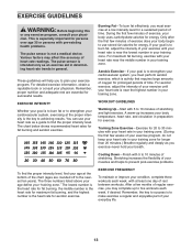
... least one day of your exercise until your heart rate is intended only as you exercise-never hold your training zone. Remember, the key to success is near the highest number in your "training zone." For aerobic exercise, adjust the intensity of your exercise until your heart rate is to five workouts each week, with pre-existing health problems. The pulse sensor is the heart rate for persons over age...
... least one day of your exercise until your heart rate is intended only as you exercise-never hold your training zone. Remember, the key to success is near the highest number in your "training zone." For aerobic exercise, adjust the intensity of your exercise until your heart rate is to five workouts each week, with pre-existing health problems. The pulse sensor is the heart rate for persons over age...
Uk Manual
Page 14
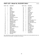
Assembly Tool Note: Specifications are not illustrated. 14 Description Key No. For information about ordering replacement parts, see the back cover of this manual. *These parts are subject to change without notice. Qty. Description 1 1 Frame 2 1 Upright 3 1 Handlebar 4 1 Seat 5 1 Console 6 1 Front Stabilizer 7 1 Rear Stabilizer 8 2 Front Cap 9 2 Rear Cap 10 1 Left Pedal/Strap 11 1 Right Pedal/Strap 12 1 Crank/Pulley 13 1 Resistance Control/Cable 14 1 Left Shield 15 1 Right Shield 16 4 M8 x 75mm Carriage Bolt 17 1 Adjustment ...
Assembly Tool Note: Specifications are not illustrated. 14 Description Key No. For information about ordering replacement parts, see the back cover of this manual. *These parts are subject to change without notice. Qty. Description 1 1 Frame 2 1 Upright 3 1 Handlebar 4 1 Seat 5 1 Console 6 1 Front Stabilizer 7 1 Rear Stabilizer 8 2 Front Cap 9 2 Rear Cap 10 1 Left Pedal/Strap 11 1 Right Pedal/Strap 12 1 Crank/Pulley 13 1 Resistance Control/Cable 14 1 Left Shield 15 1 Right Shield 16 4 M8 x 75mm Carriage Bolt 17 1 Adjustment ...
Uk Manual
Page 15
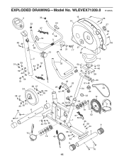
EXPLODED DRAWING-Model No. WLEVEX71209.0 R1209A 5 33 33 57 15 14 54 48 49 58 54 3 58 18 21 27 17 13 56 55 27 56 55 51 59 59 44 59 51 24 38 37 2 51 44 59 30 38 37 39 36 41 4 32 53 53 60 46 46 53 28 26 43 25 45 47 29 60 61 34 42 20 22 12 39 36 41 16 6 8 8 44 59 35 44 59 35 23 31 50 1 19 52 35 59 44 11 9 10 35 7 19 40 59 44 9 16 15
EXPLODED DRAWING-Model No. WLEVEX71209.0 R1209A 5 33 33 57 15 14 54 48 49 58 54 3 58 18 21 27 17 13 56 55 27 56 55 51 59 59 44 59 51 24 38 37 2 51 44 59 30 38 37 39 36 41 4 32 53 53 60 46 46 53 28 26 43 25 45 47 29 60 61 34 42 20 22 12 39 36 41 16 6 8 8 44 59 35 44 59 35 23 31 50 1 19 52 35 59 44 11 9 10 35 7 19 40 59 44 9 16 15
Uk Manual
Page 16
ORDERING REPLACEMENT PARTS To order replacement parts, please see the PART LIST and the EXPLODED DRAWING near the end of this manual) Part No. 290836 R1209A Printed in China © 2009 ICON IP, Inc. To help us assist you, be prepared to provide the following information when contacting us: • the model number and serial number of the product (see the front cover of this manual) • the name of the product (see the front cover of this manual) • the key number and description of the replacement part(s) (see the front cover of this manual.
ORDERING REPLACEMENT PARTS To order replacement parts, please see the PART LIST and the EXPLODED DRAWING near the end of this manual) Part No. 290836 R1209A Printed in China © 2009 ICON IP, Inc. To help us assist you, be prepared to provide the following information when contacting us: • the model number and serial number of the product (see the front cover of this manual) • the name of the product (see the front cover of this manual) • the key number and description of the replacement part(s) (see the front cover of this manual.


