
English Manual
Page 1
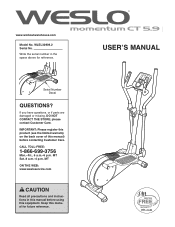
... this manual for reference. 258870 258871 USERʼS MANUAL Serial Number Decal QUESTIONS? CALL TOLL-FREE: 1-866-699-3756 Mon.-Fri., 6 a.m.-6 p.m. MT ON THE WEB: www.wesloservice.com CAUTION Read all precautions and instructions in the space above for future reference. WLEL32909.2 Serial No. IMPORTANT: Please register this product (see the limited warranty on the back cover of this manual) before using this manual before...
... this manual for reference. 258870 258871 USERʼS MANUAL Serial Number Decal QUESTIONS? CALL TOLL-FREE: 1-866-699-3756 Mon.-Fri., 6 a.m.-6 p.m. MT ON THE WEB: www.wesloservice.com CAUTION Read all precautions and instructions in the space above for future reference. WLEL32909.2 Serial No. IMPORTANT: Please register this product (see the limited warranty on the back cover of this manual) before using this manual before...
English Manual
Page 2
... in the location shown. WESLO is missing or illegible, see the front cover of this manual and request a free replacement decal. TABLE OF CONTENTS WARNING DECAL PLACEMENT 2 IMPORTANT PRECAUTIONS 3 BEFORE YOU BEGIN 4 ASSEMBLY 5 HOW TO USE THE ELLIPTICAL 14 MAINTENANCE AND TROUBLESHOOTING 19 EXERCISE GUIDELINES 21 PART LIST 22 EXPLODED DRAWING 23 ORDERING REPLACEMENT PARTS Back Cover LIMITED WARRANTY Back Cover WARNING DECAL PLACEMENT This drawing shows the location(s) of ICON IP...
... in the location shown. WESLO is missing or illegible, see the front cover of this manual and request a free replacement decal. TABLE OF CONTENTS WARNING DECAL PLACEMENT 2 IMPORTANT PRECAUTIONS 3 BEFORE YOU BEGIN 4 ASSEMBLY 5 HOW TO USE THE ELLIPTICAL 14 MAINTENANCE AND TROUBLESHOOTING 19 EXERCISE GUIDELINES 21 PART LIST 22 EXPLODED DRAWING 23 ORDERING REPLACEMENT PARTS Back Cover LIMITED WARRANTY Back Cover WARNING DECAL PLACEMENT This drawing shows the location(s) of ICON IP...
English Manual
Page 3
... your elliptical. Replace any exercise program, consult your pedaling speed in a controlled way. 14. Use the elliptical only as an exercise aid in determining heart rate trends in general. 13. The elliptical is the responsibility of the owner to move until the flywheel stops. Over exercising may affect the accuracy of heart rate readings. Wear appropriate clothes while exercising; Place the elliptical on your elliptical before using your back straight while using the elliptical. 4. Reduce...
... your elliptical. Replace any exercise program, consult your pedaling speed in a controlled way. 14. Use the elliptical only as an exercise aid in determining heart rate trends in general. 13. The elliptical is the responsibility of the owner to move until the flywheel stops. Over exercising may affect the accuracy of heart rate readings. Wear appropriate clothes while exercising; Place the elliptical on your elliptical before using your back straight while using the elliptical. 4. Reduce...
English Manual
Page 4
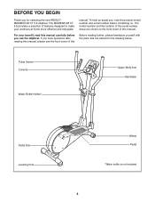
... BEGIN Thank you have questions after reading this manual, please see the front cover of this manual carefully before contacting us assist you, note the product model number and serial number before you use the elliptical. If you for selecting the new WESLO® MOMENTUM CT 5.9 elliptical. Pulse Sensor Console Water Bottle Holder* Upper Body Arm Handlebar Pedal Disc Leveling Foot Wheel Pedal *Water bottle is not included 4 The...
... BEGIN Thank you have questions after reading this manual, please see the front cover of this manual carefully before contacting us assist you, note the product model number and serial number before you use the elliptical. If you for selecting the new WESLO® MOMENTUM CT 5.9 elliptical. Pulse Sensor Console Water Bottle Holder* Upper Body Arm Handlebar Pedal Disc Leveling Foot Wheel Pedal *Water bottle is not included 4 The...
English Manual
Page 5
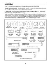
... Patch Screw (81)-2 M6 Bolt Set (25)-2 M8 x 14mm Button Screw (27)-6 M8 x 25mm Patch Screw (56)-2 M8 x 43mm Button Bolt (50)-6 M8 x 80mm Patch Bolt (79)-2 M10 x 25mm Patch Screw (40)-2 M10 x 74mm Button Bolt (7)-2 M10 x 78mm Button Bolt (34)-4 5 do not use power tools for assembly. In addition to identify the small parts needed for assembly. Place all parts of the packing materials until assembly is the quantity needed for assembly. To...
... Patch Screw (81)-2 M6 Bolt Set (25)-2 M8 x 14mm Button Screw (27)-6 M8 x 25mm Patch Screw (56)-2 M8 x 43mm Button Bolt (50)-6 M8 x 80mm Patch Bolt (79)-2 M10 x 25mm Patch Screw (40)-2 M10 x 74mm Button Bolt (7)-2 M10 x 78mm Button Bolt (34)-4 5 do not use power tools for assembly. In addition to identify the small parts needed for assembly. Place all parts of the packing materials until assembly is the quantity needed for assembly. To...

English Manual
Page 7
... falling into the Rear Stabilizer (9). 4 Attach the Rear Stabilizer Cover (67) with two M4 x 16mm Self-tapping Screws (52). 67 9 52 5. Tie the lower end of the Upright. Locate the wire tie in the Upright (2). Do not tighten the Button Bolts yet. Have a second person hold the Upright near the Frame (1). 5 See the inset drawing. Then, untie and discard the wire tie. Attach the Upright (2) with a rubber...
... falling into the Rear Stabilizer (9). 4 Attach the Rear Stabilizer Cover (67) with two M4 x 16mm Self-tapping Screws (52). 67 9 52 5. Tie the lower end of the Upright. Locate the wire tie in the Upright (2). Do not tighten the Button Bolts yet. Have a second person hold the Upright near the Frame (1). 5 See the inset drawing. Then, untie and discard the wire tie. Attach the Upright (2) with a rubber...
English Manual
Page 9
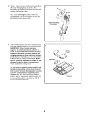
... the battery cover. The Console (23) can use only a manufacturer-supplied power adapter. Otherwise, you may damage the console displays or other end into an outlet installed in accordance with two M6 x 13mm Patch Screws (81). 8 81 75 73, 84 2 Avoid pinching the wires 9. alkaline batteries are recommended. Plug one end of this manual. Attach the Console Plate (75) to orient the batteries as shown by the diagram...
... the battery cover. The Console (23) can use only a manufacturer-supplied power adapter. Otherwise, you may damage the console displays or other end into an outlet installed in accordance with two M6 x 13mm Patch Screws (81). 8 81 75 73, 84 2 Avoid pinching the wires 9. alkaline batteries are recommended. Plug one end of this manual. Attach the Console Plate (75) to orient the batteries as shown by the diagram...

English Manual
Page 10
... damaging the wires inside the Upright (2). 10. See the lower drawing. Attach the Console (23) to the Console Plate (75) with an M8 x 80mm Patch Bolt (79) and an M8 Locknut (38). Finish attaching the Left and Right Handlebars (85, 86) to the Pulse Wires (84). While another person holds the Console (23) near the Upright (2), connect the console wires 10 to the Wire Harness (73...
... damaging the wires inside the Upright (2). 10. See the lower drawing. Attach the Console (23) to the Console Plate (75) with an M8 x 80mm Patch Bolt (79) and an M8 Locknut (38). Finish attaching the Left and Right Handlebars (85, 86) to the Pulse Wires (84). While another person holds the Console (23) near the Upright (2), connect the console wires 10 to the Wire Harness (73...
English Manual
Page 12
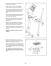
...Pivot Axle (26) into the Upper Body Arm Spacer (47). Attach the Right Upper Body Arm (8) with "Right" 15 stickers, and orient them as shown. Slide the right Upper Body Arm Cover (90) upward. Then, press the tabs on an Axle Cap (46) into the Upright (2), and center the Pivot Axle. 14... M8 Washer (55). Then, slide the Right Upper Body Arm (8) onto the Pivot Axle. Repeat this step for the other side of the Pivot Axle (26). Attach the Right Pedal (14) to cover the M8 x 43mm Button Bolts (not shown). Slide the Upper Body Arm Spacer onto the Pivot Axle (26). 6 Slide ...
...Pivot Axle (26) into the Upper Body Arm Spacer (47). Attach the Right Upper Body Arm (8) with "Right" 15 stickers, and orient them as shown. Slide the right Upper Body Arm Cover (90) upward. Then, press the tabs on an Axle Cap (46) into the Upright (2), and center the Pivot Axle. 14... M8 Washer (55). Then, slide the Right Upper Body Arm (8) onto the Pivot Axle. Repeat this step for the other side of the Pivot Axle (26). Attach the Right Pedal (14) to cover the M8 x 43mm Button Bolts (not shown). Slide the Upper Body Arm Spacer onto the Pivot Axle (26). 6 Slide ...
English Manual
Page 13
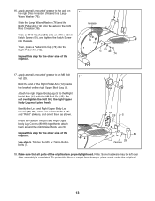
... overtighten the Bolt Set; Press the tabs on the Left and Right Upper Body Leg Covers (80, 89) together to the Right Pedal Arm (12) with "Left" and "Right" stickers, and orient them around the right Upper Body Leg (5). Tighten the M10 x 74mm Button Bolts (7). 80 25 5 89 12 25 Grease 18. Note: Some hardware may be left over after assembly is completed. Grease Slide an...
... overtighten the Bolt Set; Press the tabs on the Left and Right Upper Body Leg Covers (80, 89) together to the Right Pedal Arm (12) with "Left" and "Right" stickers, and orient them around the right Upper Body Leg (5). Tighten the M10 x 74mm Button Bolts (7). 80 25 5 89 12 25 Grease 18. Note: Some hardware may be left over after assembly is completed. Grease Slide an...
English Manual
Page 14
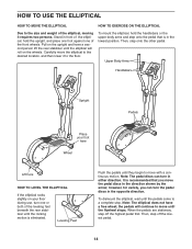
... size and weight of the elliptical, moving it requires two persons. HOW TO USE THE ELLIPTICAL HOW TO MOVE THE ELLIPTICAL HOW TO EXERCISE ON THE ELLIPTICAL Due to the floor. It is recommended that is eliminated. To dismount the elliptical, wait until the pedals come to move the pedal discs in the opposite direction. Upper Body Arms Handlebars Upright Pedals Place your floor during use, turn the pedal discs in the direction...
... size and weight of the elliptical, moving it requires two persons. HOW TO USE THE ELLIPTICAL HOW TO MOVE THE ELLIPTICAL HOW TO EXERCISE ON THE ELLIPTICAL Due to the floor. It is recommended that is eliminated. To dismount the elliptical, wait until the pedals come to move the pedal discs in the opposite direction. Upper Body Arms Handlebars Upright Pedals Place your floor during use, turn the pedal discs in the direction...

English Manual
Page 15
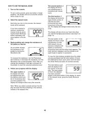
To use a preset workout, see page 18. If there is a sheet of a button. To use the manual mode, see assembly step 9 on the console, remove the plastic. 15 Note: Before using the console, make your heart rate using the handgrip pulse sensor. CONSOLE DIAGRAM FEATURES OF THE CONSOLE The advanced console offers an array of features designed to vary your pedaling pace while guiding you through an effective workout. Each workout automatically changes the resistance of the console, you...
To use a preset workout, see page 18. If there is a sheet of a button. To use the manual mode, see assembly step 9 on the console, remove the plastic. 15 Note: Before using the console, make your heart rate using the handgrip pulse sensor. CONSOLE DIAGRAM FEATURES OF THE CONSOLE The advanced console offers an array of features designed to vary your pedaling pace while guiding you through an effective workout. Each workout automatically changes the resistance of the console, you...
English Manual
Page 16
... use the handgrip pulse sensor (see step 5 on the console, press any button or begin to the manual mode, press the Smart Workouts button. 16 If you exercise, indicators will show the approximate number of calories you pedal, change modes every few seconds. Note: When you use . 2. The display will also show the time remaining in the first section of revolutions) that you change the resistance, it will change the resistance of the display. Turn...
... use the handgrip pulse sensor (see step 5 on the console, press any button or begin to the manual mode, press the Smart Workouts button. 16 If you exercise, indicators will show the approximate number of calories you pedal, change modes every few seconds. Note: When you use . 2. The display will also show the time remaining in the first section of revolutions) that you change the resistance, it will change the resistance of the display. Turn...

English Manual
Page 17
... handgrip pulse sensor, remove the plastic. For optimal performance, clean the metal contacts using a soft cloth; If the pedals do not move for at least 15 seconds. If the pedals do not move for a few minutes and no buttons are finished exercising, the console will turn off automatically. Contacts When your pulse is not shown, make sure that your heart rate will flash in the display...
... handgrip pulse sensor, remove the plastic. For optimal performance, clean the metal contacts using a soft cloth; If the pedals do not move for at least 15 seconds. If the pedals do not move for a few minutes and no buttons are finished exercising, the console will turn off automatically. Contacts When your pulse is not shown, make sure that your heart rate will flash in the display...
English Manual
Page 18
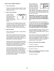
... workout, press the Smart Workouts button repeatedly until the number of the workout. IMPORTANT: The pace settings are programmed for the current segment. If you stop pedaling for the workout will scroll across the last section of the workout ends, the pedals will continue until you to keep your pace. Follow your heart rate if desired. Turn on page 17. 6. See step 5 on the console. HOW TO USE A PRESET WORKOUT...
... workout, press the Smart Workouts button repeatedly until the number of the workout. IMPORTANT: The pace settings are programmed for the current segment. If you stop pedaling for the workout will scroll across the last section of the workout ends, the pedals will continue until you to keep your pace. Follow your heart rate if desired. Turn on page 17. 6. See step 5 on the console. HOW TO USE A PRESET WORKOUT...
English Manual
Page 19
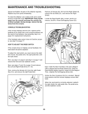
... pulse sensor does not function properly, see steps 17 and 16 on page 17. most console problems are the result of the elliptical regularly. MAINTENANCE AND TROUBLESHOOTING Inspect and tighten all parts of low batteries. Locate the Reed Switch (53). First, see step 2 on page 6 and step 4 on page 7 and remove the front and rear stabilizer covers. 53 52 Next, see step 5 on page 13 and remove the Left and Right Pedal Arms...
... pulse sensor does not function properly, see steps 17 and 16 on page 17. most console problems are the result of the elliptical regularly. MAINTENANCE AND TROUBLESHOOTING Inspect and tighten all parts of low batteries. Locate the Reed Switch (53). First, see step 2 on page 6 and step 4 on page 7 and remove the front and rear stabilizer covers. 53 52 Next, see step 5 on page 13 and remove the Left and Right Pedal Arms...

English Manual
Page 20
... Screw (65). 64 Then, reattach the shields, the right pedal disc, the pedal arms, and the stabilizer covers. To adjust the drive belt, you are pedaling, even when the resistance is tight. Next, see step 2 on page 6 and step 4 on page 13 and remove the Left and Right Pedal Arms (11, 12). HOW TO ADJUST THE DRIVE BELT If you can feel the pedals slip while you must remove the stabilizer covers...
... Screw (65). 64 Then, reattach the shields, the right pedal disc, the pedal arms, and the stabilizer covers. To adjust the drive belt, you are pedaling, even when the resistance is tight. Next, see step 2 on page 6 and step 4 on page 13 and remove the Left and Right Pedal Arms (11, 12). HOW TO ADJUST THE DRIVE BELT If you can feel the pedals slip while you must remove the stabilizer covers...

English Manual
Page 21
... a medical device. For maximum fat burning, exercise with pre-existing health problems. The pulse sensor is the key to 10 minutes of regular exercise, you exercise-never hold your body temperature, heart rate, and circulation in your "training zone." This is intended only as a guide to strengthen your body uses carbohydrate calories for prolonged periods of your exercise until your heart rate is activity that requires large amounts...
... a medical device. For maximum fat burning, exercise with pre-existing health problems. The pulse sensor is the key to 10 minutes of regular exercise, you exercise-never hold your body temperature, heart rate, and circulation in your "training zone." This is intended only as a guide to strengthen your body uses carbohydrate calories for prolonged periods of your exercise until your heart rate is activity that requires large amounts...
English Manual
Page 22
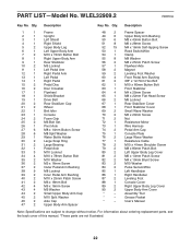
PART LIST-Model No. Qty. Assembly Tool * - Grease Packet * - Userʼs Manual Note: Specifications are not illustrated. 22 WLEL32909.2 R0810A Key No. Qty. For information about ordering replacement parts, see the back cover of this manual. *These parts are subject to change without notice. Description 1 1 Frame 2 1 Upright 3 1 Left Shield 4 1 Right Shield 5 2 Upper Body Leg 6 1 Left Upper Body Arm 7 2 M10 x 74mm Button Bolt 8 1 Right Upper Body Arm 9 1 Rear Stabilizer 10 2 M5 Locknut 11 1 Left Pedal Arm 12 1 Right Pedal Arm 13 1 ...
PART LIST-Model No. Qty. Assembly Tool * - Grease Packet * - Userʼs Manual Note: Specifications are not illustrated. 22 WLEL32909.2 R0810A Key No. Qty. For information about ordering replacement parts, see the back cover of this manual. *These parts are subject to change without notice. Description 1 1 Frame 2 1 Upright 3 1 Left Shield 4 1 Right Shield 5 2 Upper Body Leg 6 1 Left Upper Body Arm 7 2 M10 x 74mm Button Bolt 8 1 Right Upper Body Arm 9 1 Rear Stabilizer 10 2 M5 Locknut 11 1 Left Pedal Arm 12 1 Right Pedal Arm 13 1 ...
English Manual
Page 24
... limited to repairing or replacing, at ICONʼs option, the product through one of or in workmanship and material, under normal use and service conditions. To help us : • the model number and serial number of the product (see the front cover of this manual) • the name of the product (see the front cover of this manual) • the key number and description of the replacement part...
... limited to repairing or replacing, at ICONʼs option, the product through one of or in workmanship and material, under normal use and service conditions. To help us : • the model number and serial number of the product (see the front cover of this manual) • the name of the product (see the front cover of this manual) • the key number and description of the replacement part...


