
English Manual
Page 1
... CONTACT THE STORE; MT Sat. 8 a.m.-4 p.m. Serial Number Decal QUESTIONS? WLEL31808.1 Serial No. MT ON THE WEB: www.wesloservice.com CAUTION Read all precautions and instructions in the space above ) before using this manual for reference. please contact Customer Care. IMPORTANT: You must note the product model number and serial number (see the drawing above for future reference. USERʼS MANUAL www.weslo.com Model No.
... CONTACT THE STORE; MT Sat. 8 a.m.-4 p.m. Serial Number Decal QUESTIONS? WLEL31808.1 Serial No. MT ON THE WEB: www.wesloservice.com CAUTION Read all precautions and instructions in the space above ) before using this manual for reference. please contact Customer Care. IMPORTANT: You must note the product model number and serial number (see the drawing above for future reference. USERʼS MANUAL www.weslo.com Model No.
English Manual
Page 2
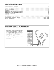
... actual size. Apply the decal in the location shown. If a decal is a registered trademark of the warning decal(s). TABLE OF CONTENTS WARNING DECAL PLACEMENT 2 IMPORTANT PRECAUTIONS 3 BEFORE YOU BEGIN 4 ASSEMBLY 5 HOW TO USE THE ELLIPTICAL EXERCISER 10 MAINTENANCE AND TROUBLESHOOTING 13 EXERCISE GUIDELINES 15 PART LIST 18 EXPLODED DRAWING 19 ORDERING REPLACEMENT PARTS Back Cover LIMITED WARRANTY Back Cover WARNING DECAL PLACEMENT This drawing shows the location(s) of ICON...
... actual size. Apply the decal in the location shown. If a decal is a registered trademark of the warning decal(s). TABLE OF CONTENTS WARNING DECAL PLACEMENT 2 IMPORTANT PRECAUTIONS 3 BEFORE YOU BEGIN 4 ASSEMBLY 5 HOW TO USE THE ELLIPTICAL EXERCISER 10 MAINTENANCE AND TROUBLESHOOTING 13 EXERCISE GUIDELINES 15 PART LIST 18 EXPLODED DRAWING 19 ORDERING REPLACEMENT PARTS Back Cover LIMITED WARRANTY Back Cover WARNING DECAL PLACEMENT This drawing shows the location(s) of ICON...
English Manual
Page 3
... it to a stop immediately and cool down. 6. Always wear athletic shoes for home use your elliptical exerciser and 2 ft. (0.6 m) on a level surface, with pre-existing health problems. 2. Do not use only. Your elliptical exerciser is the responsibility of the owner to ensure that all users of the elliptical exerciser are adequately informed of all warnings on your elliptical exerciser only as an exercise aid in determining heart rate trends in...
... it to a stop immediately and cool down. 6. Always wear athletic shoes for home use your elliptical exerciser and 2 ft. (0.6 m) on a level surface, with pre-existing health problems. 2. Do not use only. Your elliptical exerciser is the responsibility of the owner to ensure that all users of the elliptical exerciser are adequately informed of all warnings on your elliptical exerciser only as an exercise aid in determining heart rate trends in...
English Manual
Page 4
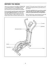
... reading further, please familiarize yourself with the parts that are shown on the front cover of this manual carefully before con- Resistance Knob Console Handlebar Shield Pedal Disc 4 Pedal BEFORE YOU BEGIN Thank you use the elliptical exerciser. To avoid a registration fee for selecting the new WESLO® MOMENTUM CT 3.8 elliptical exerciser. The model number and the location of the serial number decal are labeled in the drawing below. tacting...
... reading further, please familiarize yourself with the parts that are shown on the front cover of this manual carefully before con- Resistance Knob Console Handlebar Shield Pedal Disc 4 Pedal BEFORE YOU BEGIN Thank you use the elliptical exerciser. To avoid a registration fee for selecting the new WESLO® MOMENTUM CT 3.8 elliptical exerciser. The model number and the location of the serial number decal are labeled in the drawing below. tacting...
English Manual
Page 5
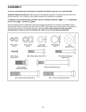
... Button Bolt (48)-2 Pedal Arm Bolt Set (40)-2 M10 x 75mm Carriage Bolt (34)-4 5 The number in parentheses below to identify the small parts needed for assembly. In addition to the included tool(s), assembly requires a Phillips screwdriver wrench , and pliers . , an adjustable See the drawings below each drawing is not in a cleared area and remove the packing materials. If a part is the key number of the part, from the PART LIST...
... Button Bolt (48)-2 Pedal Arm Bolt Set (40)-2 M10 x 75mm Carriage Bolt (34)-4 5 The number in parentheses below to identify the small parts needed for assembly. In addition to the included tool(s), assembly requires a Phillips screwdriver wrench , and pliers . , an adjustable See the drawings below each drawing is not in a cleared area and remove the packing materials. If a part is the key number of the part, from the PART LIST...

English Manual
Page 6
... the Frame (1), attach the Rear Stabilizer (28) to the Frame with two M10 x 75mm Carriage Bolts (34) and two M10 Locknuts (33). 3. Then, reattach the battery cover. 33 1 Screw Battery Cover 23 33 28 34 Batteries 6 mended. Remove the screw, remove the battery cover, and then insert four batteries into the bat- Make sure that the batteries are recom- gram inside the battery compartment. The Console (23) requires...
... the Frame (1), attach the Rear Stabilizer (28) to the Frame with two M10 x 75mm Carriage Bolts (34) and two M10 Locknuts (33). 3. Then, reattach the battery cover. 33 1 Screw Battery Cover 23 33 28 34 Batteries 6 mended. Remove the screw, remove the battery cover, and then insert four batteries into the bat- Make sure that the batteries are recom- gram inside the battery compartment. The Console (23) requires...
English Manual
Page 7
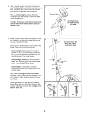
.... Console Wire 42 23 44 Avoid pinching the wires during this step 63 5. Using pliers, squeeze together the prongs on the Lower Cable (55) as shown. • See drawing C. Turn the Resistance Knob (63) counterclockwise to the lowest setting before going to the Upright (2) with two M10 x 68mm Button Bolts (48), two M10 Split Washers (59), and two M10 Locknuts (33). Do not tighten the Button Bolts...
.... Console Wire 42 23 44 Avoid pinching the wires during this step 63 5. Using pliers, squeeze together the prongs on the Lower Cable (55) as shown. • See drawing C. Turn the Resistance Knob (63) counterclockwise to the lowest setting before going to the Upright (2) with two M10 x 68mm Button Bolts (48), two M10 Split Washers (59), and two M10 Locknuts (33). Do not tighten the Button Bolts...

English Manual
Page 8
... Screws (36). Repeat this step for the Right Handlebar (8) and the other Pedal to the Upper Body Arm (5) with a "Left" sticker. 6 Insert the Left Handlebar (6) into one of the included grease to the Left Pedal Arm (11) with a "Left" sticker. 7 Attach a Pedal (13) to the left axle on the Upright (2). Identify the Left Handlebar (6), which is marked with two M6 x 38mm Button Bolts...
... Screws (36). Repeat this step for the Right Handlebar (8) and the other Pedal to the Upper Body Arm (5) with a "Left" sticker. 6 Insert the Left Handlebar (6) into one of the included grease to the Left Pedal Arm (11) with a "Left" sticker. 7 Attach a Pedal (13) to the left axle on the Upright (2). Identify the Left Handlebar (6), which is marked with two M6 x 38mm Button Bolts...
English Manual
Page 9
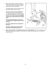
... under the elliptical exerciser. 9 Hold the lower end of the left over after assembly is completed. Apply a small amount of the axle. 8. Next, apply grease to the axle on the end of grease to a Pedal Arm Bolt Set (40). Attach the Left Pedal Arm to the right side of the elliptical exerciser are properly tightened. Make sure that all parts of the elliptical exerciser in the Upper Body Arms (5). 8 5 Grease 40 40...
... under the elliptical exerciser. 9 Hold the lower end of the left over after assembly is completed. Apply a small amount of the axle. 8. Next, apply grease to the axle on the end of grease to a Pedal Arm Bolt Set (40). Attach the Left Pedal Arm to the right side of the elliptical exerciser are properly tightened. Make sure that all parts of the elliptical exerciser in the Upper Body Arms (5). 8 5 Grease 40 40...
English Manual
Page 10
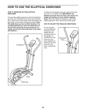
... pedal discs in the opposite direction. the pedals will continue to move until they begin to move with the resistance knob on the upright. Note: The pedal discs can adjust the resistance of the pedals with a continuous motion. When the pedals are stationary, step off the lowest pedal. HOW TO ADJUST THE PEDALING RESISTANCE As you exercise, you may turn the knob counterclockwise. to a complete stop. IMPORTANT: The elliptical exerciser does not have a free wheel; Resistance Knob Pedal Pedal...
... pedal discs in the opposite direction. the pedals will continue to move until they begin to move with the resistance knob on the upright. Note: The pedal discs can adjust the resistance of the pedals with a continuous motion. When the pedals are stationary, step off the lowest pedal. HOW TO ADJUST THE PEDALING RESISTANCE As you exercise, you may turn the knob counterclockwise. to a complete stop. IMPORTANT: The elliptical exerciser does not have a free wheel; Resistance Knob Pedal Pedal...
English Manual
Page 11
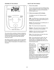
... scan mode is currently displayed. Calories-This mode shows the approximate number of calories you have burned. Scan-This mode shows the speed, time, distance, calories, and pulse modes, for use the thumb pulse sensor. Indicators To turn the power on page 6). On/Reset Button Display Button The display can even measure your workouts more effective. Note: Before using the console, make your heart rate using the pulse sensor. Note: If you have selected a different mode, press the Display button (see assembly step...
... scan mode is currently displayed. Calories-This mode shows the approximate number of calories you have burned. Scan-This mode shows the speed, time, distance, calories, and pulse modes, for use the thumb pulse sensor. Indicators To turn the power on page 6). On/Reset Button Display Button The display can even measure your workouts more effective. Note: Before using the console, make your heart rate using the pulse sensor. Note: If you have selected a different mode, press the Display button (see assembly step...

English Manual
Page 12
... is selected. To pause the console, stop pedaling and place your pulse will be detected. To continue your heart rate. 4. Do not press too hard, or the circulation in the display will flash steadily, two dashes will appear, and then your heart rate, stop pedaling. Indicators will turn off automatically. To select the speed, time, distance, or calories mode for continuous display, press the Display button repeatedly. Make sure you...
... is selected. To pause the console, stop pedaling and place your pulse will be detected. To continue your heart rate. 4. Do not press too hard, or the circulation in the display will flash steadily, two dashes will appear, and then your heart rate, stop pedaling. Indicators will turn off automatically. To select the speed, time, distance, or calories mode for continuous display, press the Display button repeatedly. Make sure you...
English Manual
Page 13
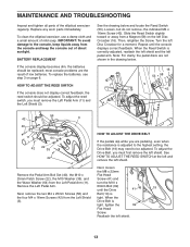
... Remove the Pedal Arm Bolt Set (40), the M10 x 25mm Patch Screw (22), the M10 Washer (35), and the Wave Washer (64) from the console and keep the console out of low batteries. HOW TO ADJUST THE DRIVE BELT If the pedals slip while you must first remove the left pedal arm. most console problems are not shown in the drawing below and locate the Reed Switch (53). Then, retighten the Screw. Next, remove...
... Remove the Pedal Arm Bolt Set (40), the M10 x 25mm Patch Screw (22), the M10 Washer (35), and the Wave Washer (64) from the console and keep the console out of low batteries. HOW TO ADJUST THE DRIVE BELT If the pedals slip while you must first remove the left pedal arm. most console problems are not shown in the drawing below and locate the Reed Switch (53). Then, retighten the Screw. Next, remove...
English Manual
Page 14
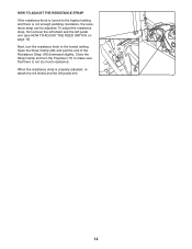
When the resistance strap is not enough pedaling resistance, the resistance strap can be adjusted. HOW TO ADJUST THE RESISTANCE STRAP If the resistance knob is turned to the highest setting and there is properly adjusted, reattach the left shield and the left pedal arm (see HOW TO ADJUST THE REED SWITCH on page 13). Open the Strap Clamp (26) and pull the end of the Resistance Strap (18) downward slightly. To adjust the resistance strap, first remove the...
When the resistance strap is not enough pedaling resistance, the resistance strap can be adjusted. HOW TO ADJUST THE RESISTANCE STRAP If the resistance knob is turned to the highest setting and there is properly adjusted, reattach the left shield and the left pedal arm (see HOW TO ADJUST THE REED SWITCH on page 13). Open the Strap Clamp (26) and pull the end of the Resistance Strap (18) downward slightly. To adjust the resistance strap, first remove the...
English Manual
Page 15
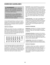
... exercise until your heart rate is to use your exercise program. Cooling Down-Finish with pre-existing health problems. The pulse sensor is near the highest number in your training zone. Only after the first few minutes of your exercise until your heart rate is not a medical device. For aerobic exercise, adjust the intensity of exercise, your physician. The three numbers listed above your age define your body begin to make exercise...
... exercise until your heart rate is to use your exercise program. Cooling Down-Finish with pre-existing health problems. The pulse sensor is near the highest number in your training zone. Only after the first few minutes of your exercise until your heart rate is not a medical device. For aerobic exercise, adjust the intensity of exercise, your physician. The three numbers listed above your age define your body begin to make exercise...

English Manual
Page 16
SUGGESTED STRETCHES The correct form for 15 counts, then relax. Allow your back and shoulders to your extended leg. Quadriceps Stretch With one hand against a wall for 15 counts, then relax. Hold for several basic stretches is shown at the right....Sit with your toes as far as possible. Reach toward your knees outward. Repeat 3 times. Bend your front leg, lean forward and move your back foot flat on the floor. Repeat 3 times. Stretches: Hamstrings, lower back and groin. 3. Hold for 15 counts, then relax. Stretches: Calves, achilles tendons and ankles. 4. ...
SUGGESTED STRETCHES The correct form for 15 counts, then relax. Allow your back and shoulders to your extended leg. Quadriceps Stretch With one hand against a wall for 15 counts, then relax. Hold for several basic stretches is shown at the right....Sit with your toes as far as possible. Reach toward your knees outward. Repeat 3 times. Bend your front leg, lean forward and move your back foot flat on the floor. Repeat 3 times. Stretches: Hamstrings, lower back and groin. 3. Hold for 15 counts, then relax. Stretches: Calves, achilles tendons and ankles. 4. ...
English Manual
Page 18
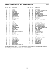
... Screw 53 1 Reed Switch/Wire 54 1 Cable Clamp 55 1 Lower Cable 56 10 M4 x 25mm Screw 57 1 M10 Flat Head Bolt 58 5 Magnet 59 2 M10 Split Washer 60 4 Large Handlebar Bushing 61 2 3/8" x 25.4mm Hex Bolt 62 1 M10 x 60mm Bolt 63 1 Resistance Knob 64 2 Wave Washer * - Userʼs Manual Note: Specifications are not illustrated. 18 Qty. Grease Packet * - WLEL31808.1 R0109A Key No. See the back cover of this manual for information...
... Screw 53 1 Reed Switch/Wire 54 1 Cable Clamp 55 1 Lower Cable 56 10 M4 x 25mm Screw 57 1 M10 Flat Head Bolt 58 5 Magnet 59 2 M10 Split Washer 60 4 Large Handlebar Bushing 61 2 3/8" x 25.4mm Hex Bolt 62 1 M10 x 60mm Bolt 63 1 Resistance Knob 64 2 Wave Washer * - Userʼs Manual Note: Specifications are not illustrated. 18 Qty. Grease Packet * - WLEL31808.1 R0109A Key No. See the back cover of this manual for information...
English Manual
Page 19
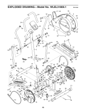
WLEL31808.1 R0109A 24 42 42 42 4 25 27 46 24 56 42 23 46 8 42 3 42 6 27 49 50 14 42 49 47 49 47 14 49 42 63 42 45 27 2 59 50 40 12 40 5 36 13 22 35 64 5 60 60 33 48 60 44 59 21 17 39 20 18 60 37 51 34 21 40 10 36 13 55 29 39 33 29 9 58 57 52 16 56 26 58 42 56 33 54 30 61 53 31 11 64 37 40 22 35 43 19 51 33 58 56 56 41 61 31 32 30 56 1 56 56 58 33 28 16 56 7 38 33 58 62 21 15 43 15 21 34 19 EXPLODED DRAWING-Model No.
WLEL31808.1 R0109A 24 42 42 42 4 25 27 46 24 56 42 23 46 8 42 3 42 6 27 49 50 14 42 49 47 49 47 14 49 42 63 42 45 27 2 59 50 40 12 40 5 36 13 22 35 64 5 60 60 33 48 60 44 59 21 17 39 20 18 60 37 51 34 21 40 10 36 13 55 29 39 33 29 9 58 57 52 16 56 26 58 42 56 33 54 30 61 53 31 11 64 37 40 22 35 43 19 51 33 58 56 56 41 61 31 32 30 56 1 56 56 58 33 28 16 56 7 38 33 58 62 21 15 43 15 21 34 19 EXPLODED DRAWING-Model No.
English Manual
Page 20
... ICON. ICON Health & Fitness, Inc., 1500 S. 1000 W., Logan, UT 84321-9813 Part No. 278198 R0109A Printed in their scope and duration to repairing or replacing, at ICONʼs option, the product through one of its authorized service centers. No other rights that specifically set forth herein. ORDERING REPLACEMENT PARTS To order replacement parts, please see the PART LIST and the EXPLODED DRAWING near the end of this manual) LIMITED WARRANTY ICON Health & Fitness...
... ICON. ICON Health & Fitness, Inc., 1500 S. 1000 W., Logan, UT 84321-9813 Part No. 278198 R0109A Printed in their scope and duration to repairing or replacing, at ICONʼs option, the product through one of its authorized service centers. No other rights that specifically set forth herein. ORDERING REPLACEMENT PARTS To order replacement parts, please see the PART LIST and the EXPLODED DRAWING near the end of this manual) LIMITED WARRANTY ICON Health & Fitness...


