

English Manual
Page 1
CALL TOLL-FREE: 1-866-699-3756 Mon.-Fri. 6 a.m.-6 p.m. MT Sat. 8 a.m.-4 p.m. www.weslo.com Model No. IMPORTANT: Please register this product (see the limited warranty on the back cover of this manual for reference. Keep this manual) before using this equipment. If you have questions, or if parts are damaged or missing, DO NOT CONTACT THE STORE; USERʼS MANUAL Serial Number Decal QUESTIONS? WLEL61808.2 Serial No...
CALL TOLL-FREE: 1-866-699-3756 Mon.-Fri. 6 a.m.-6 p.m. MT Sat. 8 a.m.-4 p.m. www.weslo.com Model No. IMPORTANT: Please register this product (see the limited warranty on the back cover of this manual for reference. Keep this manual) before using this equipment. If you have questions, or if parts are damaged or missing, DO NOT CONTACT THE STORE; USERʼS MANUAL Serial Number Decal QUESTIONS? WLEL61808.2 Serial No...
English Manual
Page 2
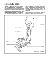
... not be shown at actual size. If a decal is a registered trademark of the warning decal(s). TABLE OF CONTENTS WARNING DECAL PLACEMENT 2 IMPORTANT PRECAUTIONS 3 BEFORE YOU BEGIN 4 ASSEMBLY 5 HOW TO USE THE ELLIPTICAL EXERCISER 10 MAINTENANCE AND TROUBLESHOOTING 13 EXERCISE GUIDELINES 15 PART LIST 18 EXPLODED DRAWING 19 ORDERING REPLACEMENT PARTS Back Cover LIMITED WARRANTY Back Cover WARNING DECAL PLACEMENT This drawing shows the location(s) of ICON IP, Inc. 2
... not be shown at actual size. If a decal is a registered trademark of the warning decal(s). TABLE OF CONTENTS WARNING DECAL PLACEMENT 2 IMPORTANT PRECAUTIONS 3 BEFORE YOU BEGIN 4 ASSEMBLY 5 HOW TO USE THE ELLIPTICAL EXERCISER 10 MAINTENANCE AND TROUBLESHOOTING 13 EXERCISE GUIDELINES 15 PART LIST 18 EXPLODED DRAWING 19 ORDERING REPLACEMENT PARTS Back Cover LIMITED WARRANTY Back Cover WARNING DECAL PLACEMENT This drawing shows the location(s) of ICON IP, Inc. 2

English Manual
Page 3
.... The pulse sensor is the responsibility of the owner to ensure that all users of the elliptical exerciser are adequately informed of all warnings on the elliptical exerciser. When you feel pain or dizziness while exercising, stop . 13. IMPORTANT PRECAUTIONS WARNING: To reduce the risk of serious injury, read all important precautions and instructions in this manual and all precautions. 8. The elliptical exerciser is especially...
.... The pulse sensor is the responsibility of the owner to ensure that all users of the elliptical exerciser are adequately informed of all warnings on the elliptical exerciser. When you feel pain or dizziness while exercising, stop . 13. IMPORTANT PRECAUTIONS WARNING: To reduce the risk of serious injury, read all important precautions and instructions in this manual and all precautions. 8. The elliptical exerciser is especially...
English Manual
Page 4
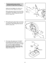
... manual, please see the front cover of the serial number decal are labeled in the drawing below. If you , note the product model number and serial number before you for selecting the new WESLO® MOMENTUM G 3.8 elliptical exerciser. The model number and the location of this manual. For your workouts at home more effective and enjoyable. BEFORE YOU BEGIN Thank you use the elliptical exerciser. Console Resistance Knob Water Bottle Holder* Shield Pedal Disc Handlebar Pedal...
... manual, please see the front cover of the serial number decal are labeled in the drawing below. If you , note the product model number and serial number before you for selecting the new WESLO® MOMENTUM G 3.8 elliptical exerciser. The model number and the location of this manual. For your workouts at home more effective and enjoyable. BEFORE YOU BEGIN Thank you use the elliptical exerciser. Console Resistance Knob Water Bottle Holder* Shield Pedal Disc Handlebar Pedal...

English Manual
Page 5
... needed for assembly. The number following the key number is completed. In addition to identify the small parts needed for assembly. Assembly requires two persons. M6 Locknut (27)-4 M10 Locknut (33)-6 M10 Split Washer (59)-2 Wave Washer (64)-2 M10 Washer (35)-2 M4 x 16mm Screw (42)-6 M6 x 45mm Flat Head Screw (36)-4 M10 x 25mm Patch Screw (22)-2 M6 x 38mm Button Bolt (50)-4 M10 x 68mm Button Bolt (48)-2 Pedal Arm Bolt Set...
... needed for assembly. The number following the key number is completed. In addition to identify the small parts needed for assembly. Assembly requires two persons. M6 Locknut (27)-4 M10 Locknut (33)-6 M10 Split Washer (59)-2 Wave Washer (64)-2 M10 Washer (35)-2 M4 x 16mm Screw (42)-6 M6 x 45mm Flat Head Screw (36)-4 M10 x 25mm Patch Screw (22)-2 M6 x 38mm Button Bolt (50)-4 M10 x 68mm Button Bolt (48)-2 Pedal Arm Bolt Set...
English Manual
Page 6
... (1), attach the Rear Stabilizer (28) to the Frame with two M10 x 75mm Carriage Bolts (34) and two M10 Locknuts (33). 33 1 3. The Console (23) requires four "AA" batteries 3 (not included); tery compartment. Make sure that the batteries are recom- Screw Battery Cover 23 33 28 34 Batteries 6 To make assembly easier, read the information on page 5 before you begin. Remove the screw, remove the battery cover, and...
... (1), attach the Rear Stabilizer (28) to the Frame with two M10 x 75mm Carriage Bolts (34) and two M10 Locknuts (33). 33 1 3. The Console (23) requires four "AA" batteries 3 (not included); tery compartment. Make sure that the batteries are recom- Screw Battery Cover 23 33 28 34 Batteries 6 To make assembly easier, read the information on page 5 before you begin. Remove the screw, remove the battery cover, and...

English Manual
Page 7
... console wire and the Upper Wire into the metal bracket on the upper end of the Resistance Cable (45) into the Frame (1). Turn the Resistance Knob (63) counterclockwise to the lowest setting before going to the Upright (2) with two M10 x 68mm Button Bolts (48), two M10 Split Washers (59), and two M10 Locknuts (33). Attach the Upright (2) with four M4 x 16mm Screws (42). Do not tighten...
... console wire and the Upper Wire into the metal bracket on the upper end of the Resistance Cable (45) into the Frame (1). Turn the Resistance Knob (63) counterclockwise to the lowest setting before going to the Upright (2) with two M10 x 68mm Button Bolts (48), two M10 Split Washers (59), and two M10 Locknuts (33). Attach the Upright (2) with four M4 x 16mm Screws (42). Do not tighten...

English Manual
Page 8
... hexagonal holes. Repeat this step with two M4 x 16mm Screws (42). 6 65 2 42 7. Attach the Water Bottle Holder (65) to the Upright (2) with the Right Handlebar (8) and the other Upper Body Arm (5). 7 6 49 14 50 5 2 Grease 47 27 Hexagonal Holes 8 5 8 Attach the Left Handlebar (6) to the left axle on the Upright (2). Do not fully tighten the Button Bolts yet. Then, tap an...
... hexagonal holes. Repeat this step with two M4 x 16mm Screws (42). 6 65 2 42 7. Attach the Water Bottle Holder (65) to the Upright (2) with the Right Handlebar (8) and the other Upper Body Arm (5). 7 6 49 14 50 5 2 Grease 47 27 Hexagonal Holes 8 5 8 Attach the Left Handlebar (6) to the left axle on the Upright (2). Do not fully tighten the Button Bolts yet. Then, tap an...

English Manual
Page 9
... over after assembly is marked with a "Left" sticker. 8 Attach a Pedal (13) to the Left Pedal Arm (11) with the Pedal Arm Bolt Set (40). See step 5. Make sure that all parts of the axle. Identify the Left Pedal Arm (11), which is completed. Apply a small amount of grease to the right side of the left Disc Crossbar (16). Next, tighten an M10 x 25mm Patch Screw (22...
... over after assembly is marked with a "Left" sticker. 8 Attach a Pedal (13) to the Left Pedal Arm (11) with the Pedal Arm Bolt Set (40). See step 5. Make sure that all parts of the axle. Identify the Left Pedal Arm (11), which is completed. Apply a small amount of grease to the right side of the left Disc Crossbar (16). Next, tighten an M10 x 25mm Patch Screw (22...

English Manual
Page 10
... the opposite direction. HOW TO ADJUST THE PEDALING RESISTANCE As you exercise, you may turn the knob counterclockwise. to move until the flywheel stops. Resistance Knob Pedal Pedal Disc 10 Push the pedals until the pedals come to move with the resistance knob on the upright. IMPORTANT: The elliptical exerciser does not have a free wheel; HOW TO USE THE ELLIPTICAL EXERCISER HOW TO EXERCISE ON THE ELLIPTICAL EXERCISER To mount the elliptical exerciser, hold the handlebars and step onto the pedal that...
... the opposite direction. HOW TO ADJUST THE PEDALING RESISTANCE As you exercise, you may turn the knob counterclockwise. to move until the flywheel stops. Resistance Knob Pedal Pedal Disc 10 Push the pedals until the pedals come to move with the resistance knob on the upright. IMPORTANT: The elliptical exerciser does not have a free wheel; HOW TO USE THE ELLIPTICAL EXERCISER HOW TO EXERCISE ON THE ELLIPTICAL EXERCISER To mount the elliptical exerciser, hold the handlebars and step onto the pedal that...

English Manual
Page 11
.../Reset Button Display Button The display can even measure your approximate pedaling pace in revolutions per minute (rpm). Distance-This mode shows the distance (total number of revolutions) you pedal, the console will then be displayed only when you have burned. Note: If you have pedaled. the console will provide continuous exercise feedback. Thumb Pulse Sensor The console offers a selection of the display indicates your heart rate using the pulse sensor. Pulse-This mode shows your workouts more...
.../Reset Button Display Button The display can even measure your approximate pedaling pace in revolutions per minute (rpm). Distance-This mode shows the distance (total number of revolutions) you pedal, the console will then be displayed only when you have burned. Note: If you have pedaled. the console will provide continuous exercise feedback. Thumb Pulse Sensor The console offers a selection of the display indicates your heart rate using the pulse sensor. Pulse-This mode shows your workouts more...

English Manual
Page 12
... reset the display, press the On/Reset button. Measure your pulse will show which mode is not an indicator below the word Scan. Indicators will not be reset. 12 After a few seconds. Try the pulse sensor several times until you are finished exercising, the console will be restricted and your heart rate if desired. To continue your heart rate will turn off automatically. To pause the console, stop pedaling and...
... reset the display, press the On/Reset button. Measure your pulse will show which mode is not an indicator below the word Scan. Indicators will not be reset. 12 After a few seconds. Try the pulse sensor several times until you are finished exercising, the console will be restricted and your heart rate if desired. To continue your heart rate will turn off automatically. To pause the console, stop pedaling and...

English Manual
Page 13
... Flat Head Screw (41) and turn the M10 x 60mm Bolt (62) until the console displays correct feedback. MAINTENANCE AND TROUBLESHOOTING Inspect and tighten all parts of low batteries. IMPORTANT: To avoid damage to be replaced; When the Reed Switch is adjusted to the highest setting, the Drive Belt (19) may need to the console, keep the console out of mild soap. Gently remove the Left Shield. To replace the batteries, see step 3 on the...
... Flat Head Screw (41) and turn the M10 x 60mm Bolt (62) until the console displays correct feedback. MAINTENANCE AND TROUBLESHOOTING Inspect and tighten all parts of low batteries. IMPORTANT: To avoid damage to be replaced; When the Reed Switch is adjusted to the highest setting, the Drive Belt (19) may need to the console, keep the console out of mild soap. Gently remove the Left Shield. To replace the batteries, see step 3 on the...

English Manual
Page 14
... highest setting and there is not too much resistance. To adjust the resistance strap, first remove the left shield and the left pedal arm. 26 18 17 14 Open the Strap Clamp (26) and pull the end of the Resistance Strap (18) downward slightly. Close the Strap Clamp and turn the resistance knob to make sure that there is not enough pedaling resistance, the resistance strap can be adjusted. When the resistance strap...
... highest setting and there is not too much resistance. To adjust the resistance strap, first remove the left shield and the left pedal arm. 26 18 17 14 Open the Strap Clamp (26) and pull the end of the Resistance Strap (18) downward slightly. Close the Strap Clamp and turn the resistance knob to make sure that there is not enough pedaling resistance, the resistance strap can be adjusted. When the resistance strap...

English Manual
Page 15
...-exercise problems. To find the proper intensity level, find the proper intensity level. The three numbers listed above your age define your everyday life. 15 EXERCISE FREQUENCY To maintain or improve your cardiovascular system, you may affect the accuracy of your "training zone." Remember, the key to success is intended only as a guide to find your body begin to use...
...-exercise problems. To find the proper intensity level, find the proper intensity level. The three numbers listed above your age define your everyday life. 15 EXERCISE FREQUENCY To maintain or improve your cardiovascular system, you may affect the accuracy of your "training zone." Remember, the key to success is intended only as a guide to find your body begin to use...
English Manual
Page 16
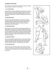
... feet toward your knees outward. Bring the sole of the achilles tendons, bend your buttocks as possible. Stretches: Hamstrings, lower back and groin. 3. Keep your back leg straight and your hips. Bring your heel as close to relax as you reach down toward your groin area as far ...4. Hold for several basic stretches is shown at the right. Stretches: Quadriceps and hip muscles. 3 5 1 2 4 16 SUGGESTED STRETCHES The correct form for 15 counts, then relax. Bend your front leg, lean forward and move your toes as far as you and rest it against a wall for 15 counts, then relax...
... feet toward your knees outward. Bring the sole of the achilles tendons, bend your buttocks as possible. Stretches: Hamstrings, lower back and groin. 3. Keep your back leg straight and your hips. Bring your heel as close to relax as you reach down toward your groin area as far ...4. Hold for several basic stretches is shown at the right. Stretches: Quadriceps and hip muscles. 3 5 1 2 4 16 SUGGESTED STRETCHES The correct form for 15 counts, then relax. Bend your front leg, lean forward and move your toes as far as you and rest it against a wall for 15 counts, then relax...

English Manual
Page 18
... Screw Disc Cover Upper Wire Resistance Control/Cable Handlebar Cap Handlebar Spacer M10 x 68mm Button Bolt Small Handlebar Bushing M6 x 38mm Button Bolt Inner Pedal Arm Bushing M4 x 16mm Flat Head Screw Reed Switch/Wire Cable Clamp Lower Cable M4 x 25mm Screw M10 Flat Head Bolt Magnet M10 Split Washer Large Handlebar Bushing 3/8" x 25.4mm Hex Bolt M10 x 60mm Bolt Resistance Knob Wave Washer Water Bottle Holder Assembly Tool Grease Packet Userʼs Manual Note: Specifications are not illustrated. 18 PART LIST-Model...
... Screw Disc Cover Upper Wire Resistance Control/Cable Handlebar Cap Handlebar Spacer M10 x 68mm Button Bolt Small Handlebar Bushing M6 x 38mm Button Bolt Inner Pedal Arm Bushing M4 x 16mm Flat Head Screw Reed Switch/Wire Cable Clamp Lower Cable M4 x 25mm Screw M10 Flat Head Bolt Magnet M10 Split Washer Large Handlebar Bushing 3/8" x 25.4mm Hex Bolt M10 x 60mm Bolt Resistance Knob Wave Washer Water Bottle Holder Assembly Tool Grease Packet Userʼs Manual Note: Specifications are not illustrated. 18 PART LIST-Model...

English Manual
Page 19
WLEL61808.2 R0409A 24 46 42 42 42 4 25 27 46 56 42 23 42 8 3 42 49 47 49 14 42 6 42 27 47 49 50 2 14 49 5 60 60 34 33 44 21 10 21 36 40 13 51 11 64 37 40 22 35 43 19 63 42 45 27 50 40 12 40 36 13 42 5 65 59 22 35 64 48 60 59 60 17 39 20 18 37 51 55 29 39 33 29 9 58 57 52 16 56 26 58 42 56 33 54 30 61 53 31 33 58 56 56 41 31 32 1 61 30 56 56 58 33 16 56 7 38 33 58 62 21 15 56 28 43 15 21 34 19 EXPLODED DRAWING-Model No.
WLEL61808.2 R0409A 24 46 42 42 42 4 25 27 46 56 42 23 42 8 3 42 49 47 49 14 42 6 42 27 47 49 50 2 14 49 5 60 60 34 33 44 21 10 21 36 40 13 51 11 64 37 40 22 35 43 19 63 42 45 27 50 40 12 40 36 13 42 5 65 59 22 35 64 48 60 59 60 17 39 20 18 37 51 55 29 39 33 29 9 58 57 52 16 56 26 58 42 56 33 54 30 61 53 31 33 58 56 56 41 31 32 1 61 30 56 56 58 33 16 56 7 38 33 58 62 21 15 56 28 43 15 21 34 19 EXPLODED DRAWING-Model No.

English Manual
Page 20
... 84321-9813 Part No. 280593 R0409A Printed in -home service, the customer will be responsible for service needed under normal use , or costs of incidental or consequential damages. To help us : • the model number and serial number of the product (see the front cover of this manual) • the name of the product (see the front cover of this manual. ICON Health & Fitness, Inc. (ICON) warrants this...
... 84321-9813 Part No. 280593 R0409A Printed in -home service, the customer will be responsible for service needed under normal use , or costs of incidental or consequential damages. To help us : • the model number and serial number of the product (see the front cover of this manual) • the name of the product (see the front cover of this manual. ICON Health & Fitness, Inc. (ICON) warrants this...


