
English Manual
Page 1
www.weslo.com Model No. Serial Number Decal (under frame) QUESTIONS? CALL TOLL-FREE: 1-866-699-3756 Mon.–-Fri. 6 a.m.–-6 p.m. Write the serial number in this manual before contacting Customer Care. If you have questions, or if parts are damaged or missing,...all precautions and instructions in the space above for future reference. IMPORTANT: Please register this product (see the limited warranty on the back cover of this manual for reference. MT Sat. 8 a.m.–-4 p.m. WLEL32112.0 Serial No. USER’'S MANUAL Keep this manual) before using this equipment....
www.weslo.com Model No. Serial Number Decal (under frame) QUESTIONS? CALL TOLL-FREE: 1-866-699-3756 Mon.–-Fri. 6 a.m.–-6 p.m. Write the serial number in this manual before contacting Customer Care. If you have questions, or if parts are damaged or missing,...all precautions and instructions in the space above for future reference. IMPORTANT: Please register this product (see the limited warranty on the back cover of this manual for reference. MT Sat. 8 a.m.–-4 p.m. WLEL32112.0 Serial No. USER’'S MANUAL Keep this manual) before using this equipment....
English Manual
Page 2
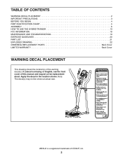
... of the warning decal(s). Apply the decal in the location shown. TABLE OF CONTENTS WARNING DECAL PLACEMENT 2 IMPORTANT PRECAUTIONS 3 BEFORE YOU BEGIN 4 PART IDENTIFICATION CHART 5 ASSEMBLY 6 HOW TO USE THE HYBRID TRAINER 13 FCC INFORMATION 18 MAINTENANCE AND TROUBLESHOOTING 19 EXERCISE GUIDELINES 20 PART LIST 21 EXPLODED DRAWING 22 ORDERING REPLACEMENT PARTS Back Cover LIMITED WARRANTY Back Cover WARNING DECAL PLACEMENT This drawing shows the location(s) of ICON IP, Inc. 2
... of the warning decal(s). Apply the decal in the location shown. TABLE OF CONTENTS WARNING DECAL PLACEMENT 2 IMPORTANT PRECAUTIONS 3 BEFORE YOU BEGIN 4 PART IDENTIFICATION CHART 5 ASSEMBLY 6 HOW TO USE THE HYBRID TRAINER 13 FCC INFORMATION 18 MAINTENANCE AND TROUBLESHOOTING 19 EXERCISE GUIDELINES 20 PART LIST 21 EXPLODED DRAWING 22 ORDERING REPLACEMENT PARTS Back Cover LIMITED WARRANTY Back Cover WARNING DECAL PLACEMENT This drawing shows the location(s) of ICON IP, Inc. 2
English Manual
Page 3
... feel faint or if you use only. Use the hybrid trainer only as an exercise aid in determining heart rate trends in general. 14. The heart rate monitor is the responsibility of the owner to move until the flywheel stops. Various factors may result in serious injury or death. do not wear loose clothes that the pedal knobs are adequately informed of all times. 16...
... feel faint or if you use only. Use the hybrid trainer only as an exercise aid in determining heart rate trends in general. 14. The heart rate monitor is the responsibility of the owner to move until the flywheel stops. Various factors may result in serious injury or death. do not wear loose clothes that the pedal knobs are adequately informed of all times. 16...
English Manual
Page 4
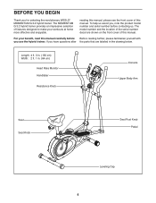
... the revolutionary WESLO® MOMENTUM G 3.2 hybrid trainer. reading this manual, please see the front cover of this manual. The model number and the location of features designed to make your benefit, read this manual. For your workouts at home more effective and enjoyable. The MOMENTUM G 3.2 hybrid trainer provides an impressive selection of the serial number decal are labeled in . (64 cm) Heart Rate Monitor Handlebar Resistance Knob Console Upper Body Arm Seat Seat Knob Seat Post Knob Pedal Leveling Cap...
... the revolutionary WESLO® MOMENTUM G 3.2 hybrid trainer. reading this manual, please see the front cover of this manual. The model number and the location of features designed to make your benefit, read this manual. For your workouts at home more effective and enjoyable. The MOMENTUM G 3.2 hybrid trainer provides an impressive selection of the serial number decal are labeled in . (64 cm) Heart Rate Monitor Handlebar Resistance Knob Console Upper Body Arm Seat Seat Knob Seat Post Knob Pedal Leveling Cap...
English Manual
Page 5
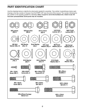
PART IDENTIFICATION CHART Use the drawings below each drawing is the key number of the part, from the PART LIST near the end of this manual. Extra parts may be included. Note: If a part is the quantity needed for assembly. M8 Locknut (53)–-3 M8 Acorn Nut (58)–-8 M10 Locknut (93)–-6 Left Crank Locknut (37)–-1 Right Crank Locknut (36)–-1 M8 Split M8...
PART IDENTIFICATION CHART Use the drawings below each drawing is the key number of the part, from the PART LIST near the end of this manual. Extra parts may be included. Note: If a part is the quantity needed for assembly. M8 Locknut (53)–-3 M8 Acorn Nut (58)–-8 M10 Locknut (93)–-6 Left Crank Locknut (37)–-1 Right Crank Locknut (36)–-1 M8 Split M8...
English Manual
Page 6
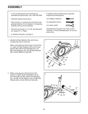
...;• To identify small parts, see page 5. •• In addition to the included tool(s), assembly requires the following tools: one Phillips screwdriver one adjustable wrench one rubber mallet Assembly may be easier if you have a set of the Frame (1), attach the Front Stabilizer (10) to 2 the Frame with two M8 x 65mm Carriage Bolts (51), two M8...
...;• To identify small parts, see page 5. •• In addition to the included tool(s), assembly requires the following tools: one Phillips screwdriver one adjustable wrench one rubber mallet Assembly may be easier if you have a set of the Frame (1), attach the Front Stabilizer (10) to 2 the Frame with two M8 x 65mm Carriage Bolts (51), two M8...
English Manual
Page 7
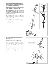
... drawing B. Attach the Upright (2) with two M8 x 60mm Bolts (90), four M8 Washers (55), and two M8 Locknuts (53). Using pliers, squeeze together the prongs on the Lower Cable (42). Do not tighten the Screws yet. Next, connect the Resistance Cable (25) to the Reed Switch Wire (47). Tip: Avoid pinching the wires and cables during this step. Pull upward on the metal bracket on the Lower Cable (42...
... drawing B. Attach the Upright (2) with two M8 x 60mm Bolts (90), four M8 Washers (55), and two M8 Locknuts (53). Using pliers, squeeze together the prongs on the Lower Cable (42). Do not tighten the Screws yet. Next, connect the Resistance Cable (25) to the Reed Switch Wire (47). Tip: Avoid pinching the wires and cables during this step. Pull upward on the metal bracket on the Lower Cable (42...
English Manual
Page 9
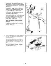
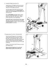
... Right Upper Body Arm (6) onto the right axle on the Upright (2) and to the left Pedal Arm (11) in the same way. Attach the Right Pedal (12) to the right axle on the Upright (2). Orient the Right Pedal and the right 8 Pedal Arm as shown. Attach the Left Pedal (13) to a Wave Washer (73). 7. Next, orient an Upright Spacer (26) as shown. Press an 8mm...
... Right Upper Body Arm (6) onto the right axle on the Upright (2) and to the left Pedal Arm (11) in the same way. Attach the Right Pedal (12) to the right axle on the Upright (2). Orient the Right Pedal and the right 8 Pedal Arm as shown. Attach the Left Pedal (13) to a Wave Washer (73). 7. Next, orient an Upright Spacer (26) as shown. Press an 8mm...
English Manual
Page 10
.... Note: Turn the Left Crank Axle (not shown) counterclockwise to a Wave Washer (73). Press a 17mm Dome Cap (14) firmly onto each M10 Washer (92). Apply grease to an M10 x 70mm Bolt (60). 10 Attach the right Pedal Arm (11) to the left side of the Crank (18). Then...step on the left Upper Body Leg (64) in the same way. 64 11 14 93 64 92 62 92 60 14 11 Grease 10 Identify the Right Crank Axle (16). Note: Place the Plastic Washers between the right Upper Body Leg and the right Pedal Arm. Apply grease to the Right Crank Axle (16) and to tighten it, and use the Left Crank...
.... Note: Turn the Left Crank Axle (not shown) counterclockwise to a Wave Washer (73). Press a 17mm Dome Cap (14) firmly onto each M10 Washer (92). Apply grease to an M10 x 70mm Bolt (60). 10 Attach the right Pedal Arm (11) to the left side of the Crank (18). Then...step on the left Upper Body Leg (64) in the same way. 64 11 14 93 64 92 62 92 60 14 11 Grease 10 Identify the Right Crank Axle (16). Note: Place the Plastic Washers between the right Upper Body Leg and the right Pedal Arm. Apply grease to the Right Crank Axle (16) and to tighten it, and use the Left Crank...
English Manual
Page 11
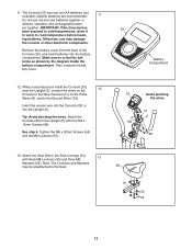
... step 4. Attach the Seat (69) to the Ground Wire (102). Remove the battery cover from the back of the Console (23), and insert batteries into the Upright (2). Tighten the M8 x 20mm Screws (54) and the M8 Locknuts (53). 23 Battery Compartment 23 Avoid pinching the wires A 102 31 2 66 13. While a second person holds the Console (23) near the Upright (2), connect the wires on the 12 Console to the Wire...
... step 4. Attach the Seat (69) to the Ground Wire (102). Remove the battery cover from the back of the Console (23), and insert batteries into the Upright (2). Tighten the M8 x 20mm Screws (54) and the M8 Locknuts (53). 23 Battery Compartment 23 Avoid pinching the wires A 102 31 2 66 13. While a second person holds the Console (23) near the Upright (2), connect the wires on the 12 Console to the Wire...
English Manual
Page 13
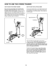
... on the upright and have a free wheel; Then, step onto the other pedal. When the pedals are stationary, step off the lower pedal. 13 To mount the hybrid trainer in the elliptical mode, hold the upright, and place one foot against one of the front stabilizer caps. Then, step off the higher pedal first. Carefully move with a continuous motion. Note: The crank arms can turn in the direction shown...
... on the upright and have a free wheel; Then, step onto the other pedal. When the pedals are stationary, step off the lower pedal. 13 To mount the hybrid trainer in the elliptical mode, hold the upright, and place one foot against one of the front stabilizer caps. Then, step off the higher pedal first. Carefully move with a continuous motion. Note: The crank arms can turn in the direction shown...
English Manual
Page 14
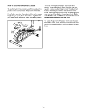
... seat post knob is inserted into the frame and the seat post, and then tighten the seat post knob. Seat Post Knob To adjust the position of the seat, first loosen and remove the seat post knob. For effective exercise, the seat should be at the proper height. To adjust the height of the seat, first loosen the seat knob a few turns. HOW TO USE THE UPRIGHT BIKE MODE To use the hybrid trainer as an upright bike, adjust...
... seat post knob is inserted into the frame and the seat post, and then tighten the seat post knob. Seat Post Knob To adjust the position of the seat, first loosen and remove the seat post knob. For effective exercise, the seat should be at the proper height. To adjust the height of the seat, first loosen the seat knob a few turns. HOW TO USE THE UPRIGHT BIKE MODE To use the hybrid trainer as an upright bike, adjust...
English Manual
Page 15
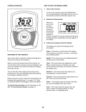
...;-This mode shows the distance you use the manual mode of the display will provide continuous exercise feedback. The display will turn on page 11). The display can even measure your pedaling speed. To use the handgrip heart rate monitor. Calories—-This mode shows the approximate number of features designed to make sure that prompt you through an effective workout. This display shows your workouts more effective. CONSOLE DIAGRAM HOW TO USE THE MANUAL MODE 1. Speed...
...;-This mode shows the distance you use the manual mode of the display will provide continuous exercise feedback. The display will turn on page 11). The display can even measure your pedaling speed. To use the handgrip heart rate monitor. Calories—-This mode shows the approximate number of features designed to make sure that prompt you through an effective workout. This display shows your workouts more effective. CONSOLE DIAGRAM HOW TO USE THE MANUAL MODE 1. Speed...
English Manual
Page 16
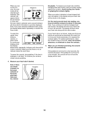
... to hold the handgrip heart rate monitor, the display will be reset. 4. Measure your workout, simply resume pedaling. To select the speed, time, distance, calories, or pulse mode for up to move for about 15 seconds. Be careful not to 30 seconds. Note: If there are positioned as described. To pause the console, stop pedaling. For optimal performance, clean the contacts using a soft cloth; Make sure...
... to hold the handgrip heart rate monitor, the display will be reset. 4. Measure your workout, simply resume pedaling. To select the speed, time, distance, calories, or pulse mode for up to move for about 15 seconds. Be careful not to 30 seconds. Note: If there are positioned as described. To pause the console, stop pedaling. For optimal performance, clean the contacts using a soft cloth; Make sure...
English Manual
Page 17
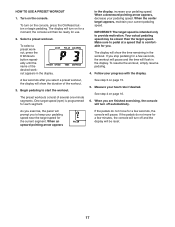
... desired workout appears in the display, increase your pedaling speed near the target speed for the current segment. See step 3 on the console, press the On/Reset button or begin pedaling. the console will flash in the workout. A few minutes, the console will turn on page 15. 5. If you . IMPORTANT: The target speed is comfortable for you stop pedaling for use. 2. HOW TO USE A PRESET WORKOUT 1. One target speed (rpm) is programmed for...
... desired workout appears in the display, increase your pedaling speed near the target speed for the current segment. See step 3 on the console, press the On/Reset button or begin pedaling. the console will flash in the workout. A few minutes, the console will turn on page 15. 5. If you . IMPORTANT: The target speed is comfortable for you stop pedaling for use. 2. HOW TO USE A PRESET WORKOUT 1. One target speed (rpm) is programmed for...

English Manual
Page 18
... FCC Rules. These limits are designed to provide reasonable protection against harmful interference in a particular installation. FCC INFORMATION This equipment has been tested and found to comply with the instructions, may cause harmful interference to radio communications. This equipment generates, uses, and can be determined by turning the equipment off and on, the user is no guarantee...
... FCC Rules. These limits are designed to provide reasonable protection against harmful interference in a particular installation. FCC INFORMATION This equipment has been tested and found to comply with the instructions, may cause harmful interference to radio communications. This equipment generates, uses, and can be determined by turning the equipment off and on, the user is no guarantee...
English Manual
Page 19
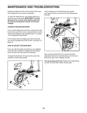
.... MAINTENANCE AND TROUBLESHOOTING Inspect and tighten all the batteries at the left. If the console does not display your heart rate when you can feel the pedals slip while you are the result of mild soap. HOW TO ADJUST THE DRIVE BELT If you can reach the Idler Adjustment Bolt (34). See the drawing at the same time; CONSOLE TROUBLESHOOTING If the console display becomes dim, replace all parts of direct sunlight...
.... MAINTENANCE AND TROUBLESHOOTING Inspect and tighten all the batteries at the left. If the console does not display your heart rate when you can feel the pedals slip while you are the result of mild soap. HOW TO ADJUST THE DRIVE BELT If you can reach the Idler Adjustment Bolt (34). See the drawing at the same time; CONSOLE TROUBLESHOOTING If the console display becomes dim, replace all parts of direct sunlight...
English Manual
Page 20
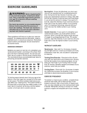
... burn fat, adjust the intensity of your training zone for longer than 20 minutes.) Breathe regularly and deeply as a guide to plan your cardiovascular system, exercising at a low intensity level for a sustained period of heart rate readings. EXERCISE GUIDELINES WARNING: Before beginning this or any exercise program, consult your body uses carbohydrate calories for energy. This is the key to the nearest...
... burn fat, adjust the intensity of your training zone for longer than 20 minutes.) Breathe regularly and deeply as a guide to plan your cardiovascular system, exercising at a low intensity level for a sustained period of heart rate readings. EXERCISE GUIDELINES WARNING: Before beginning this or any exercise program, consult your body uses carbohydrate calories for energy. This is the key to the nearest...
English Manual
Page 21
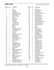
... Pedal 14 4 17mm Dome Cap 15 1 Left Crank Axle 16 1 Right Crank Axle 17 1 Flywheel 18 1 Crank 19 1 Drive Belt 20 1 Crank Bearing Assembly 21 2 Front Stabilizer Cap 22 1 Frame Sleeve 23 1 Console 24 1 Seat Post 25 1 Resistance Control/Cable 26 2 Upright Spacer 27 4 M8 Plastic Washer 28 1 Rear Stabilizer 29 3 Large Flywheel Bearing 30 2 Seat Post Sleeve 31 1 Wire Harness 32 1 Pulley 33 2 Leveling Cap 34 1 Idler Adjustment Bolt...
... Pedal 14 4 17mm Dome Cap 15 1 Left Crank Axle 16 1 Right Crank Axle 17 1 Flywheel 18 1 Crank 19 1 Drive Belt 20 1 Crank Bearing Assembly 21 2 Front Stabilizer Cap 22 1 Frame Sleeve 23 1 Console 24 1 Seat Post 25 1 Resistance Control/Cable 26 2 Upright Spacer 27 4 M8 Plastic Washer 28 1 Rear Stabilizer 29 3 Large Flywheel Bearing 30 2 Seat Post Sleeve 31 1 Wire Harness 32 1 Pulley 33 2 Leveling Cap 34 1 Idler Adjustment Bolt...
English Manual
Page 24
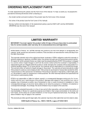
... free from the date of purchase. damages with the use and service conditions. To help us : •• the model number and serial number of the product (see the front cover of this manual) •• the name of the product (see the front cover of this manual) •• the key number and description of the replacement part(s) (see the front cover of its authorized service...
... free from the date of purchase. damages with the use and service conditions. To help us : •• the model number and serial number of the product (see the front cover of this manual) •• the name of the product (see the front cover of this manual) •• the key number and description of the replacement part(s) (see the front cover of its authorized service...


