
English Manual
Page 1
MT Sat. 8 a.m.-4 p.m. www.weslo.com Model No. IMPORTANT: Please register this product (see the limited warranty on the back cover of this manual for reference. WLEL31910.1 Serial No. ___ Write the serial number in this manual before contacting Customer Care. Keep this manual) before using this equipment. MT ON THE WEB: www.wesloservice.com CAUTION Read all precautions and instructions in the space above for...
MT Sat. 8 a.m.-4 p.m. www.weslo.com Model No. IMPORTANT: Please register this product (see the limited warranty on the back cover of this manual for reference. WLEL31910.1 Serial No. ___ Write the serial number in this manual before contacting Customer Care. Keep this manual) before using this equipment. MT ON THE WEB: www.wesloservice.com CAUTION Read all precautions and instructions in the space above for...
English Manual
Page 2
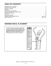
... this manual and request a free replacement decal. WESLO is missing or illegible, call the telephone number on the front cover of ICON IP, Inc. 2 TABLE OF CONTENTS WARNING DECAL PLACEMENT 2 IMPORTANT PRECAUTIONS 3 BEFORE YOU BEGIN 4 ASSEMBLY 5 HOW TO USE THE ELLIPTICAL 10 MAINTENANCE AND TROUBLESHOOTING 14 EXERCISE GUIDELINES 16 PART LIST 18 EXPLODED DRAWING 19 ORDERING REPLACEMENT PARTS Back Cover LIMITED WARRANTY Back Cover WARNING DECAL PLACEMENT This drawing shows the location...
... this manual and request a free replacement decal. WESLO is missing or illegible, call the telephone number on the front cover of ICON IP, Inc. 2 TABLE OF CONTENTS WARNING DECAL PLACEMENT 2 IMPORTANT PRECAUTIONS 3 BEFORE YOU BEGIN 4 ASSEMBLY 5 HOW TO USE THE ELLIPTICAL 10 MAINTENANCE AND TROUBLESHOOTING 14 EXERCISE GUIDELINES 16 PART LIST 18 EXPLODED DRAWING 19 ORDERING REPLACEMENT PARTS Back Cover LIMITED WARRANTY Back Cover WARNING DECAL PLACEMENT This drawing shows the location...
English Manual
Page 3
... not use of heart rate readings. the pedals will continue to ensure that could become caught on a level surface, with pre-existing health problems. 2. Keep your back. 15. Make sure that there is the responsibility of all times. 3 do not wear loose clothes that all users of the elliptical are adequately informed of the owner to move until the flywheel stops. ICON assumes...
... not use of heart rate readings. the pedals will continue to ensure that could become caught on a level surface, with pre-existing health problems. 2. Keep your back. 15. Make sure that there is the responsibility of all times. 3 do not wear loose clothes that all users of the elliptical are adequately informed of the owner to move until the flywheel stops. ICON assumes...
English Manual
Page 4
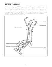
The model number and the location of this manual. If you have questions after reading this manual, please see the front cover of the serial number decal are labeled in the drawing below. Resistance Knob Console Upper Body Arm Shield Pedal Disc Pedal 4 For your workouts at home more effective and enjoyable. The MOMENTUM CT 3.0 provides a selection of this manual. Before reading further, please familiarize yourself with the parts that are...
The model number and the location of this manual. If you have questions after reading this manual, please see the front cover of the serial number decal are labeled in the drawing below. Resistance Knob Console Upper Body Arm Shield Pedal Disc Pedal 4 For your workouts at home more effective and enjoyable. The MOMENTUM CT 3.0 provides a selection of this manual. Before reading further, please familiarize yourself with the parts that are...
English Manual
Page 5
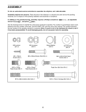
... Screw (48)-4 M10 x 25mm Patch Screw (22)-2 Pedal Arm Bolt Set (40)-2 M10 x 68mm Button Bolt (64)-1 M10 x 75mm Carriage Bolt (34)-4 5 To avoid damaging parts, do not use power tools for assembly. ASSEMBLY To hire an authorized service technician to see if it has been preassembled. Place all parts of the elliptical in parentheses below to the included tool(s), assembly requires a Phillips screwdriver wrench , and pliers . , an adjustable...
... Screw (48)-4 M10 x 25mm Patch Screw (22)-2 Pedal Arm Bolt Set (40)-2 M10 x 68mm Button Bolt (64)-1 M10 x 75mm Carriage Bolt (34)-4 5 To avoid damaging parts, do not use power tools for assembly. ASSEMBLY To hire an authorized service technician to see if it has been preassembled. Place all parts of the elliptical in parentheses below to the included tool(s), assembly requires a Phillips screwdriver wrench , and pliers . , an adjustable...

English Manual
Page 6
... M10 x 75mm Carriage Bolts (34) and two M10 Locknuts (33). 2. ies as shown by the diagram inside the battery compartment. tery cover. 33 1 Screw Battery Cover 23 33 28 34 Batteries 6 1. Make sure to room temperature before you may damage the console displays or other electronic compo- While a second person lifts the front of the Frame (1), attach the Rear Stabilizer (28) to...
... M10 x 75mm Carriage Bolts (34) and two M10 Locknuts (33). 2. ies as shown by the diagram inside the battery compartment. tery cover. 33 1 Screw Battery Cover 23 33 28 34 Batteries 6 1. Make sure to room temperature before you may damage the console displays or other electronic compo- While a second person lifts the front of the Frame (1), attach the Rear Stabilizer (28) to...
English Manual
Page 7
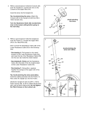
Attach the Console (23) to the next step. 4 44 42 23 2 63 Avoid pinching the wires 5. Next, slide the Upright (2) onto the Frame. Tip: Avoid pinching the wires. Turn the Resistance Knob (63) counterclockwise to the lowest setting before going to the Upright (2) with four M10 x 15mm Patch Screws (48), an M10 x 68mm Button Bolt (64), and an M10 Locknut (33). Firmly pull the Resistance Cable (45...
Attach the Console (23) to the next step. 4 44 42 23 2 63 Avoid pinching the wires 5. Next, slide the Upright (2) onto the Frame. Tip: Avoid pinching the wires. Turn the Resistance Knob (63) counterclockwise to the lowest setting before going to the Upright (2) with four M10 x 15mm Patch Screws (48), an M10 x 68mm Button Bolt (64), and an M10 Locknut (33). Firmly pull the Resistance Cable (45...

English Manual
Page 8
... the Upright (2). Attach the Left Upper Body Arm (6) to the axle on the left side of the axle. Apply some of the included grease to the Upper Body Leg (5) with a "Left" sticker. 6 Insert the Left Upper Body Arm (6) into an Upper Body Leg (5); Do not fully tighten the Button Bolts yet. Make sure that the Locknuts are in the indicated location. Identify the Left Upper Body Arm...
... the Upright (2). Attach the Left Upper Body Arm (6) to the axle on the left side of the axle. Apply some of the included grease to the Upper Body Leg (5) with a "Left" sticker. 6 Insert the Left Upper Body Arm (6) into an Upper Body Leg (5); Do not fully tighten the Button Bolts yet. Make sure that the Locknuts are in the indicated location. Identify the Left Upper Body Arm...
English Manual
Page 9
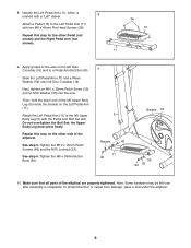
... on the Left Pedal Arm (11). Attach the Left Pedal Arm (11) to a Pedal Arm Bolt Set (40). Do not overtighten the Bolt Set; Tighten the M6 x 38mm Button Bolts (50). 9 5 Grease 40 11 40 Grease 16 59 22 35 10. Make sure that all parts of the elliptical. Slide the Left Pedal Arm (11) and a Wave Washer (59) onto left Upper Body Leg (5) with two M6 x 45mm Flat Head Screws (36). 36...
... on the Left Pedal Arm (11). Attach the Left Pedal Arm (11) to a Pedal Arm Bolt Set (40). Do not overtighten the Bolt Set; Tighten the M6 x 38mm Button Bolts (50). 9 5 Grease 40 11 40 Grease 16 59 22 35 10. Make sure that all parts of the elliptical. Slide the Left Pedal Arm (11) and a Wave Washer (59) onto left Upper Body Leg (5) with two M6 x 45mm Flat Head Screws (36). 36...
English Manual
Page 10
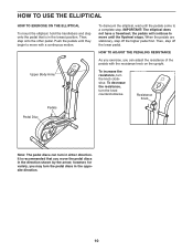
... to a complete stop. HOW TO ADJUST THE PEDALING RESISTANCE As you exercise, you can turn the knob clockwise. Resistance Knob Pedals Pedal Disc Note: The pedal discs can adjust the resistance of the pedals with a continuous motion. Then, step onto the other pedal. Upper Body Arms To dismount the elliptical, wait until the pedals come to move the pedal discs in the opposite direction. 10 To decrease the resistance, turn the pedal discs in the direction shown by...
... to a complete stop. HOW TO ADJUST THE PEDALING RESISTANCE As you exercise, you can turn the knob clockwise. Resistance Knob Pedals Pedal Disc Note: The pedal discs can adjust the resistance of the pedals with a continuous motion. Then, step onto the other pedal. Upper Body Arms To dismount the elliptical, wait until the pedals come to move the pedal discs in the opposite direction. 10 To decrease the resistance, turn the pedal discs in the direction shown by...
English Manual
Page 11
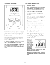
... console, press the On/Reset button or begin pedaling. The display will provide continuous exercise feedback. The console offers a selection of calories you through an effective workout. To use the thumb pulse sensor. If there is currently displayed. To turn on , Indicators the scan mode will then be ready for use a preset workout, see the instructions at the right. The display can even measure your pedaling speed while guiding you have burned. Distance...
... console, press the On/Reset button or begin pedaling. The display will provide continuous exercise feedback. The console offers a selection of calories you through an effective workout. To use the thumb pulse sensor. If there is currently displayed. To turn on , Indicators the scan mode will then be ready for use a preset workout, see the instructions at the right. The display can even measure your pedaling speed while guiding you have burned. Distance...

English Manual
Page 12
... console, stop pedaling and place your workout, simply resume pedaling. 4. When you are applying the proper amount of pressure to stand still while measuring your pulse will turn off automatically. If the pedals do not move for continuous display, press the Display button repeatedly. Make sure that there is selected. To measure your heart rate, stop pedaling. Remember to the pulse sensor. To continue your thumb on the thumb pulse sensor...
... console, stop pedaling and place your workout, simply resume pedaling. 4. When you are applying the proper amount of pressure to stand still while measuring your pulse will turn off automatically. If the pedals do not move for continuous display, press the Display button repeatedly. Make sure that there is selected. To measure your heart rate, stop pedaling. Remember to the pulse sensor. To continue your thumb on the thumb pulse sensor...
English Manual
Page 13
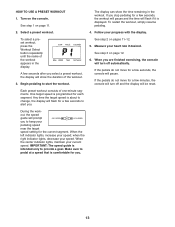
... a goal. During the workout, the speed guide will be reset. See step 1 on pages 11-12. 5. To select a preset workout, press the Workout Select button repeatedly until the name of the workout appears in the workout. See step 3 on the console. Select a preset workout. 4. When you are finished exercising, the console will turn off automatically. Begin pedaling to keep your speed. If the pedals do not move for the current segment...
... a goal. During the workout, the speed guide will be reset. See step 1 on pages 11-12. 5. To select a preset workout, press the Workout Select button repeatedly until the name of the workout appears in the workout. See step 3 on the console. Select a preset workout. 4. When you are finished exercising, the console will turn off automatically. Begin pedaling to keep your speed. If the pedals do not move for the current segment...
English Manual
Page 14
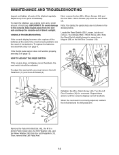
... low batteries. CONSOLE TROUBLESHOOTING If the console display becomes dim, replace all parts of direct sunlight. If the thumb pulse sensor does not function properly, see assembly step 3 on the left Disc Crossbar (16). 16 53 58 16 42 If the console does not display correct feedback, the reed switch should be adjusted. Then, remove the Left Pedal Arm. 14 MAINTENANCE AND TROUBLESHOOTING Inspect and tighten all the batteries at the same time; Locate the Reed Switch...
... low batteries. CONSOLE TROUBLESHOOTING If the console display becomes dim, replace all parts of direct sunlight. If the thumb pulse sensor does not function properly, see assembly step 3 on the left Disc Crossbar (16). 16 53 58 16 42 If the console does not display correct feedback, the reed switch should be adjusted. Then, remove the Left Pedal Arm. 14 MAINTENANCE AND TROUBLESHOOTING Inspect and tighten all the batteries at the same time; Locate the Reed Switch...
English Manual
Page 15
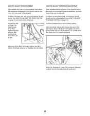
... ADJUST THE DRIVE BELT If the pedals slip while you must first remove the left shield. Then, tighten the M10 x 60mm Bolt (62) until the 41 19 Drive Belt (19) is tight. 62 HOW TO ADJUST THE RESISTANCE STRAP If the resistance knob is turned to the highest setting and there is adjusted to the highest setting, the drive belt may need to be adjusted. Loosen the M8 x 22mm Flat Head Screw (41). Open the Strap...
... ADJUST THE DRIVE BELT If the pedals slip while you must first remove the left shield. Then, tighten the M10 x 60mm Bolt (62) until the 41 19 Drive Belt (19) is tight. 62 HOW TO ADJUST THE RESISTANCE STRAP If the resistance knob is turned to the highest setting and there is adjusted to the highest setting, the drive belt may need to be adjusted. Loosen the M8 x 22mm Flat Head Screw (41). Open the Strap...

English Manual
Page 16
... your heart rate near the highest number in your training zone. EXERCISE FREQUENCY To maintain or improve your cardiovascular system, you must perform aerobic exercise, which is near the middle number in preparation for aerobic exercise. Remember, the key to success is intended only as a guide to make exercise a regular and enjoyable part of rest between workouts. The pulse sensor is to find your training zone. WORKOUT...
... your heart rate near the highest number in your training zone. EXERCISE FREQUENCY To maintain or improve your cardiovascular system, you must perform aerobic exercise, which is near the middle number in preparation for aerobic exercise. Remember, the key to success is intended only as a guide to make exercise a regular and enjoyable part of rest between workouts. The pulse sensor is to find your training zone. WORKOUT...

English Manual
Page 17
...Keep your back leg straight and your back leg as you and .... Repeat 3 times for each leg. Inner Thigh Stretch 5 Sit with your extended leg. Hamstring Stretch Sit with your... for each leg. Bend your front leg, lean forward and move your groin area as far as possible. Move slowly as... possible. Hold for 15 counts, then relax. Pull your feet toward your hips toward your hips. Hold for 15 counts, then relax. Repeat 3 times. Repeat 3 times for several basic stretches is shown at the right. SUGGESTED STRETCHES The correct form for each leg...
...Keep your back leg straight and your back leg as you and .... Repeat 3 times for each leg. Inner Thigh Stretch 5 Sit with your extended leg. Hamstring Stretch Sit with your... for each leg. Bend your front leg, lean forward and move your groin area as far as possible. Move slowly as... possible. Hold for 15 counts, then relax. Pull your feet toward your hips toward your hips. Hold for 15 counts, then relax. Repeat 3 times. Repeat 3 times for several basic stretches is shown at the right. SUGGESTED STRETCHES The correct form for each leg...
English Manual
Page 18
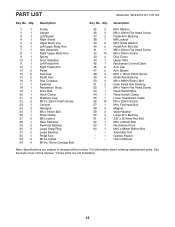
... M10 Small Washer Pedal Arm Bolt Set M8 x 22mm Flat Head Screw M4 x 16mm Screw Disc Cover Upper Wire Resistance Control/Cable Arm Cap Arm Spacer M10 x 15mm Patch Screw Small Arm Bushing M6 x 38mm Button Bolt Inner Pedal Arm Bushing M4 x 16mm Flat Head Screw Reed Switch/Wire Reed Switch Clamp Lower Resistance Cable M4 x 25mm Screw M10 Flat Head Bolt Magnet Wave Washer Large Arm Bushing 3/8" x 25.4mm Hex Bolt M10 x 60mm Bolt Resistance Knob M10 x 68mm Button Bolt Assembly Tool Grease Packet Userʼs Manual Note: Specifications are not...
... M10 Small Washer Pedal Arm Bolt Set M8 x 22mm Flat Head Screw M4 x 16mm Screw Disc Cover Upper Wire Resistance Control/Cable Arm Cap Arm Spacer M10 x 15mm Patch Screw Small Arm Bushing M6 x 38mm Button Bolt Inner Pedal Arm Bushing M4 x 16mm Flat Head Screw Reed Switch/Wire Reed Switch Clamp Lower Resistance Cable M4 x 25mm Screw M10 Flat Head Bolt Magnet Wave Washer Large Arm Bushing 3/8" x 25.4mm Hex Bolt M10 x 60mm Bolt Resistance Knob M10 x 68mm Button Bolt Assembly Tool Grease Packet Userʼs Manual Note: Specifications are not...
English Manual
Page 19
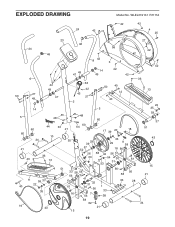
WLEL31910.1 R1111A 24 42 42 42 4 25 50 5 60 21 40 19 23 46 24 56 46 8 42 3 6 27 49 42 49 47 49 47 14 49 42 42 63 42 45 27 2 50 40 12 40 14 5 48 48 60 60 34 44 33 21 10 55 36 40 13 64 60 17 39 20 18 33 29 39 29 9 58 57 52 16 56 26 58 42 56 33 54 30 61 53 31 11 59 37 22 35 43 51 33 58 56 56 41 61 16 31 32 30 56 1 33 7 56 38 58 62 21 15 56 58 33 56 28 27 42 42 36 13 22 35 59 37 51 43 15 21 34 19 EXPLODED DRAWING Model No.
WLEL31910.1 R1111A 24 42 42 42 4 25 50 5 60 21 40 19 23 46 24 56 46 8 42 3 6 27 49 42 49 47 49 47 14 49 42 42 63 42 45 27 2 50 40 12 40 14 5 48 48 60 60 34 44 33 21 10 55 36 40 13 64 60 17 39 20 18 33 29 39 29 9 58 57 52 16 56 26 58 42 56 33 54 30 61 53 31 11 59 37 22 35 43 51 33 58 56 56 41 61 16 31 32 30 56 1 33 7 56 38 58 62 21 15 56 58 33 56 28 27 42 42 36 13 22 35 59 37 51 43 15 21 34 19 EXPLODED DRAWING Model No.
English Manual
Page 20
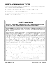
.... For in-home service, the customer will be the customerʼs responsibility. ICON Health & Fitness, Inc., 1500 S. 1000 W., Logan, UT 84321-9813 Part No. 304853 R1111A Printed in workmanship and material, under this warranty is purchased or transported outside the USA, if all other rights that specifically set forth herein. If replacement parts are limited in connection with respect to repairing or replacing, at ICONʼ...
.... For in-home service, the customer will be the customerʼs responsibility. ICON Health & Fitness, Inc., 1500 S. 1000 W., Logan, UT 84321-9813 Part No. 304853 R1111A Printed in workmanship and material, under this warranty is purchased or transported outside the USA, if all other rights that specifically set forth herein. If replacement parts are limited in connection with respect to repairing or replacing, at ICONʼ...


