
Uk Manual
Page 1
As a manufacturer, we are missing or damaged parts, please call: 08457 089 009 Or write: ICON Health & Fitness, Ltd. Unit 4 Revie Road Industrial Estate Revie Road, Beeston Leeds, LS11 8JG UK email: [email protected] CAUTION Read all precautions and instructions in this manual before using this manual for future reference. Keep this equipment. USER'S MANUAL Visit our website at www.iconeurope.com WLEVEL1976.0 Serial No. If you have questions, or if there are committed to providing complete customer satisfaction. Model No. Serial Number Decal QUESTIONS?
As a manufacturer, we are missing or damaged parts, please call: 08457 089 009 Or write: ICON Health & Fitness, Ltd. Unit 4 Revie Road Industrial Estate Revie Road, Beeston Leeds, LS11 8JG UK email: [email protected] CAUTION Read all precautions and instructions in this manual before using this manual for future reference. Keep this equipment. USER'S MANUAL Visit our website at www.iconeurope.com WLEVEL1976.0 Serial No. If you have questions, or if there are committed to providing complete customer satisfaction. Model No. Serial Number Decal QUESTIONS?
Uk Manual
Page 2
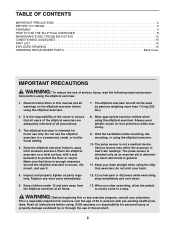
... BEGIN 3 ASSEMBLY 4 HOW TO USE THE ELLIPTICAL EXERCISER 8 MAINTENANCE AND TROUBLESHOOTING 12 CONDITIONING GUIDELINES 13 PART LIST 14 EXPLODED DRAWING 15 ORDERING REPLACEMENT PARTS Back Cover IMPORTANT PRECAUTIONS WARNING: To reduce the risk of heart rate readings. Always wear athletic shoes for home use it to ensure that there is intended only as an exercise aid in determining heart rate trends in a commercial, rental, or institutional setting. 4. The pulse sensor is...
... BEGIN 3 ASSEMBLY 4 HOW TO USE THE ELLIPTICAL EXERCISER 8 MAINTENANCE AND TROUBLESHOOTING 12 CONDITIONING GUIDELINES 13 PART LIST 14 EXPLODED DRAWING 15 ORDERING REPLACEMENT PARTS Back Cover IMPORTANT PRECAUTIONS WARNING: To reduce the risk of heart rate readings. Always wear athletic shoes for home use it to ensure that there is intended only as an exercise aid in determining heart rate trends in a commercial, rental, or institutional setting. 4. The pulse sensor is...
Uk Manual
Page 3
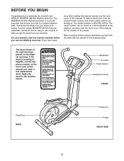
... cover of this manual for selecting the versatile new WESLO® MOMENTUM 605 elliptical exerciser. And the unique MOMENTUM 605 features adjustable resistance and an easy-to help us . For your knees and ankles. The MOMENTUM 605 elliptical exerciser is WLEVEL1976.0. Handlebar Console Pulse Sensor Resistance Knob FRONT Pedal Disc BACK Pedal Arm Pedal RIGHT SIDE 3 The decal shown at the right has been placed on your benefit, read this manual and order a free replacement decal. The model number...
... cover of this manual for selecting the versatile new WESLO® MOMENTUM 605 elliptical exerciser. And the unique MOMENTUM 605 features adjustable resistance and an easy-to help us . For your knees and ankles. The MOMENTUM 605 elliptical exerciser is WLEVEL1976.0. Handlebar Console Pulse Sensor Resistance Knob FRONT Pedal Disc BACK Pedal Arm Pedal RIGHT SIDE 3 The decal shown at the right has been placed on your benefit, read this manual and order a free replacement decal. The model number...
Uk Manual
Page 4
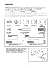
... Button Bolt (50)-4 Pedal Arm Bolt Set (40)-2 M10 x 68mm Button Bolt (48)-2 M10 x 70mm Carriage Bolt (34)-4 1. If a part is completed. Place all parts of the part, from the PART LIST on page 14. Note: Some small parts may have been preassembled. In addition to see if it has been preassembled. ASSEMBLY Assembly requires two persons. The number in the parts bag, check to the included hex keys, assembly requires...
... Button Bolt (50)-4 Pedal Arm Bolt Set (40)-2 M10 x 68mm Button Bolt (48)-2 M10 x 70mm Carriage Bolt (34)-4 1. If a part is completed. Place all parts of the part, from the PART LIST on page 14. Note: Some small parts may have been preassembled. In addition to see if it has been preassembled. ASSEMBLY Assembly requires two persons. The number in the parts bag, check to the included hex keys, assembly requires...
Uk Manual
Page 5
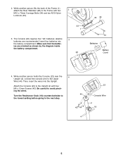
... Turn the Resistance Knob (18) counterclockwise to the lowest setting before going to the Upright (2) with two 2 M10 x 70mm Carriage Bolts (34) and two M10 Nylon Locknuts (33). 33 1 3. While another person holds the Console (23) near the 4 Upright (2), connect the console wire to the Frame with four M6 x 12mm Screws (43). While another person lifts the back of the Frame (1), attach the Rear...
... Turn the Resistance Knob (18) counterclockwise to the lowest setting before going to the Upright (2) with two 2 M10 x 70mm Carriage Bolts (34) and two M10 Nylon Locknuts (33). 33 1 3. While another person holds the Console (23) near the 4 Upright (2), connect the console wire to the Frame with four M6 x 12mm Screws (43). While another person lifts the back of the Frame (1), attach the Rear...

Uk Manual
Page 6
... on the Upright (2) as shown. • See drawing C. Apply a small amount of the included grease to the Reed Switch Wire (53). Make sure that the Handlebar Arm is turned so the hexagonal holes are not pinched during 1 this step to pinch the wires or cables. B 45 20 C 45 Metal Bracket 20 8 2 Grease 5 47 27 Hexagonal Holes 5 6 Firmly pull the Resistance Cable (45) and...
... on the Upright (2) as shown. • See drawing C. Apply a small amount of the included grease to the Reed Switch Wire (53). Make sure that the Handlebar Arm is turned so the hexagonal holes are not pinched during 1 this step to pinch the wires or cables. B 45 20 C 45 Metal Bracket 20 8 2 Grease 5 47 27 Hexagonal Holes 5 6 Firmly pull the Resistance Cable (45) and...
Uk Manual
Page 7
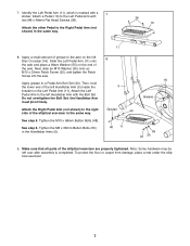
... Button Bolts (50) in the Handlebar Arms (5). 40 11 55 22 35 9. 7. Slide the Left Pedal Arm (11) onto the axle and place a Wave Washer (55) on the left over after assembly is marked with 7 two M6 x 48mm Flat Head Screws (36). Make sure that all parts of the axle. Then, hold the lower end of grease to a Pedal Arm Bolt Set (40). See step...
... Button Bolts (50) in the Handlebar Arms (5). 40 11 55 22 35 9. 7. Slide the Left Pedal Arm (11) onto the axle and place a Wave Washer (55) on the left over after assembly is marked with 7 two M6 x 48mm Flat Head Screws (36). Make sure that all parts of the axle. Then, hold the lower end of grease to a Pedal Arm Bolt Set (40). See step...
Uk Manual
Page 8
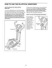
... decrease the resistance, turn the pedal discs in the opposite direction. Then, step off the highest pedal first. Handlebars To dismount the elliptical exerciser, wait until the flywheel stops. When the pedals are stationary, step off the lower pedal. Resistance Knob Pedal Pedal Disc 8 however, for variety, you can turn the knob clockwise; To increase the resistance, turn in either direction. to move until the pedals come to move with the resistance knob on the upright. It is...
... decrease the resistance, turn the pedal discs in the opposite direction. Then, step off the highest pedal first. Handlebars To dismount the elliptical exerciser, wait until the flywheel stops. When the pedals are stationary, step off the lower pedal. Resistance Knob Pedal Pedal Disc 8 however, for variety, you can turn the knob clockwise; To increase the resistance, turn in either direction. to move until the pedals come to move with the resistance knob on the upright. It is...
Uk Manual
Page 9
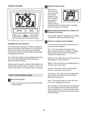
... number of calories you use the handgrip pulse sensor. Scan-When you pedal, adjust the resistance of the elapsed time. You can even measure your progress with the display. Distance-This mode shows the distance that you have burned (see assembly step 3 on page 13). To turn on the display, remove the plastic. 4 Follow your heart rate using the console, make your heart rate when you have pedaled, in the display. 3 Begin pedaling and change the resistance...
... number of calories you use the handgrip pulse sensor. Scan-When you pedal, adjust the resistance of the elapsed time. You can even measure your progress with the display. Distance-This mode shows the distance that you have burned (see assembly step 3 on page 13). To turn on the display, remove the plastic. 4 Follow your heart rate using the console, make your heart rate when you have pedaled, in the display. 3 Begin pedaling and change the resistance...
Uk Manual
Page 10
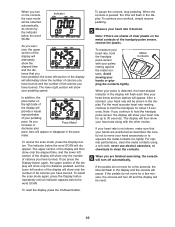
... of the display will turn off automatically. The display will show the number of your pedaling speed. To reset the display, press the On/Reset button. 10 To pause the console, stop pedaling. Note: If there are finished exercising, the console will provide a visual representation of calories you have burned. To continue your workout, simply resume pedaling. 5 Measure your pulse is detected, the heart-shaped indicator in the display. the lower left...
... of the display will turn off automatically. The display will show the number of your pedaling speed. To reset the display, press the On/Reset button. 10 To pause the console, stop pedaling. Note: If there are finished exercising, the console will provide a visual representation of calories you have burned. To continue your workout, simply resume pedaling. 5 Measure your pulse is detected, the heart-shaped indicator in the display. the lower left...
Uk Manual
Page 11
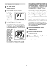
... of the display. See step 5 on the right side of the two pace programs. To select a pace program, press the Pace Programs button repeatedly until P1 or P2 appears in the program. See step 6 on the console. Note: The same target pace setting may be shown by turning the resistance knob. Important: The target pace settings for consecutive periods. During the program, adjust the resistance of the pedals as...
... of the display. See step 5 on the right side of the two pace programs. To select a pace program, press the Pace Programs button repeatedly until P1 or P2 appears in the program. See step 6 on the console. Note: The same target pace setting may be shown by turning the resistance knob. Important: The target pace settings for consecutive periods. During the program, adjust the resistance of the pedals as...
Uk Manual
Page 12
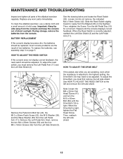
... reed switch should be replaced; Remove the Left Pedal Arm. Loosen, but do not remove, the indicated M4 x 16mm Screw (42). Next, loosen the M8 x 22mm Flat Head Screw (41) and turn the M10 x 60mm 19 Bolt (62) until the console displays correct feedback. most console problems are pedaling, even when the resistance is 41 tight. Repeat until the Drive Belt (19) is adjusted to the highest setting, the Drive Belt (19) may need...
... reed switch should be replaced; Remove the Left Pedal Arm. Loosen, but do not remove, the indicated M4 x 16mm Screw (42). Next, loosen the M8 x 22mm Flat Head Screw (41) and turn the M10 x 60mm 19 Bolt (62) until the console displays correct feedback. most console problems are pedaling, even when the resistance is 41 tight. Repeat until the Drive Belt (19) is adjusted to the highest setting, the Drive Belt (19) may need...
Uk Manual
Page 13
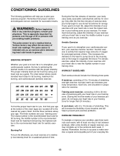
... burn fat, adjust the intensity of your exercise until your heart rate is near the lowest number in your everyday life. 13 After a few minutes of your exercise until your age at a relatively low intensity level for exercise. Remember, the key to use stored fat calories for longer than 20 minutes.) A cool-down, with pre-existing health problems. The pulse sensor is to...
... burn fat, adjust the intensity of your exercise until your heart rate is near the lowest number in your everyday life. 13 After a few minutes of your exercise until your age at a relatively low intensity level for exercise. Remember, the key to use stored fat calories for longer than 20 minutes.) A cool-down, with pre-existing health problems. The pulse sensor is to...
Uk Manual
Page 14
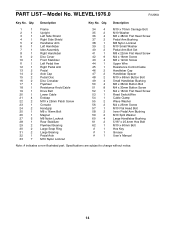
... x 36mm Button Bolt 51 8 M4 x 30mm Button Screw 52 1 M4 x 16mm Flat Head Screw 53 1 Reed Switch/Wire 54 1 Cable Clamp 55 2 Wave Washer 56 2 M4 x 25mm Screw 57 1 M10 Flat Head Bolt 58 2 Inner Pedal Arm Bushing 59 2 M10 Split Washer 60 4 Large Handlebar Bushing 61 2 5/16" x 25.4mm Hex Bolt 62 1 M10 x 60mm Bolt # 1 Hex Key # 1 Grease # 1 User's Manual Note: # indicates a non-illustrated part. PART LIST-Model No. Qty. Qty. Specifications are...
... x 36mm Button Bolt 51 8 M4 x 30mm Button Screw 52 1 M4 x 16mm Flat Head Screw 53 1 Reed Switch/Wire 54 1 Cable Clamp 55 2 Wave Washer 56 2 M4 x 25mm Screw 57 1 M10 Flat Head Bolt 58 2 Inner Pedal Arm Bushing 59 2 M10 Split Washer 60 4 Large Handlebar Bushing 61 2 5/16" x 25.4mm Hex Bolt 62 1 M10 x 60mm Bolt # 1 Hex Key # 1 Grease # 1 User's Manual Note: # indicates a non-illustrated part. PART LIST-Model No. Qty. Qty. Specifications are...
Uk Manual
Page 15
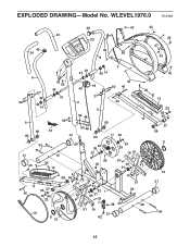
EXPLODED DRAWING-Model No. WLEVEL1976.0 R1206A 24 46 24 46 23 42 8 42 56 42 4 25 27 42 6 27 49 50 14 5 60 60 43 52 49 47 33 44 21 49 47 3 49 14 18 45 42 50 40 27 2 5 59 48 59 48 60 40 60 17 39 36 12 34 21 40 10 36 13 20 29 39 57 33 29 16 51 26 51 33 30 61 31 11 55 37 40 35 22 42 58 53 33 51 54 41 32 1 61 30 31 51 7 38 33 19 9 15 51 16 21 62 51 33 28 42 13 22 35 55 37 58 9 15 21 34 15
EXPLODED DRAWING-Model No. WLEVEL1976.0 R1206A 24 46 24 46 23 42 8 42 56 42 4 25 27 42 6 27 49 50 14 5 60 60 43 52 49 47 33 44 21 49 47 3 49 14 18 45 42 50 40 27 2 5 59 48 59 48 60 40 60 17 39 36 12 34 21 40 10 36 13 20 29 39 57 33 29 16 51 26 51 33 30 61 31 11 55 37 40 35 22 42 58 53 33 51 54 41 32 1 61 30 31 51 7 38 33 19 9 15 51 16 21 62 51 33 28 42 13 22 35 55 37 58 9 15 21 34 15
Uk Manual
Page 16
... R1206A Printed in China © 2006 ICON IP, Inc. office, or write: ICON Health & Fitness, Ltd. ORDERING REPLACEMENT PARTS To order replacement parts, contact the ICON Health & Fitness, Ltd. Customer Service Department Unit 4, Revie Road Industrial Estate ...information: • the MODEL NUMBER of the product (WLEVEL1976.0) • the NAME of the product (WESLO MOMENTUM 605 elliptical exerciser) • the SERIAL NUMBER of the product (see the front cover of this manual) • the KEY NUMBER and DESCRIPTION of the part(s) (see pages 14 and 15) WESLO is a registered trademark of ICON...
... R1206A Printed in China © 2006 ICON IP, Inc. office, or write: ICON Health & Fitness, Ltd. ORDERING REPLACEMENT PARTS To order replacement parts, contact the ICON Health & Fitness, Ltd. Customer Service Department Unit 4, Revie Road Industrial Estate ...information: • the MODEL NUMBER of the product (WLEVEL1976.0) • the NAME of the product (WESLO MOMENTUM 605 elliptical exerciser) • the SERIAL NUMBER of the product (see the front cover of this manual) • the KEY NUMBER and DESCRIPTION of the part(s) (see pages 14 and 15) WESLO is a registered trademark of ICON...


