

Uk Manual
Page 3
... away from heated surfaces. 14. If an extension cord is needed, use . (See the drawing on page 5 for both men and women. Always remove the key, unplug the power cord, and move the walking belt whilst the power is not working properly. (See TROUBLESHOOTING on the walking belt. Do not operate the treadmill where aerosol products are adequately informed of all times. 7. IMPORTANT PRECAUTIONS WARNING: To reduce...
... away from heated surfaces. 14. If an extension cord is needed, use . (See the drawing on page 5 for both men and women. Always remove the key, unplug the power cord, and move the walking belt whilst the power is not working properly. (See TROUBLESHOOTING on the walking belt. Do not operate the treadmill where aerosol products are adequately informed of all times. 7. IMPORTANT PRECAUTIONS WARNING: To reduce...

Uk Manual
Page 4
.... DANGER: 24. Never remove the motor hood unless instructed to do so by or through the use only. ICON assumes no responsibility for in this or any opening. The treadmill is not legible, call the telephone number on the treadmill. Always unplug the power cord immediately after use the treadmill in a commercial, rental, or institutional setting. Servicing other than the procedures in -home use of this product. Do...
.... DANGER: 24. Never remove the motor hood unless instructed to do so by or through the use only. ICON assumes no responsibility for in this or any opening. The treadmill is not legible, call the telephone number on the treadmill. Always unplug the power cord immediately after use the treadmill in a commercial, rental, or institutional setting. Servicing other than the procedures in -home use of this product. Do...

Uk Manual
Page 5
... Tray Handrail Storage Latch Bookrack Console Key/Clip Upright RIGHT SIDE Walking Belt Foot Rail BACK Rear Roller Adjustment Bolts On/Off Switch Circuit Breaker Walking Platform 5 The CADENCE 1000 FM treadmill combines advanced technology with the parts that are labelled in the privacy of other treadmills. ing this manual for selecting the new WESLO® CADENCE 1000 FM treadmill. To help you get the most from your exercise in the drawing...
... Tray Handrail Storage Latch Bookrack Console Key/Clip Upright RIGHT SIDE Walking Belt Foot Rail BACK Rear Roller Adjustment Bolts On/Off Switch Circuit Breaker Walking Platform 5 The CADENCE 1000 FM treadmill combines advanced technology with the parts that are labelled in the privacy of other treadmills. ing this manual for selecting the new WESLO® CADENCE 1000 FM treadmill. To help you get the most from your exercise in the drawing...

Uk Manual
Page 6
...) to the Base (79) in the indicated location. Note: There is lubricant on top. Assembly requires the included hex keys cutters , and needlenose pliers and your own phillips screwdriver . , wire For help of this manual. 1. Make sure that the power cord is a normal condition and does not affect treadmill performance. Attach the Left Upright (47) to a vertical position. 2 57 47 Pivot...
...) to the Base (79) in the indicated location. Note: There is lubricant on top. Assembly requires the included hex keys cutters , and needlenose pliers and your own phillips screwdriver . , wire For help of this manual. 1. Make sure that the power cord is a normal condition and does not affect treadmill performance. Attach the Left Upright (47) to a vertical position. 2 57 47 Pivot...

Uk Manual
Page 7
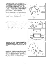
... Upright (47) with 4 two 3/4" Screws (38). Identify the Right Handrail (40), which has a pulse bar bracket on the Right Handrail (40) into the large bracket on the left side. Feed the Wire Harness (65) up into the upper end of the large hole in the Latch...Bolt. Then, remove the 4" Frame Bolt. Have a second person lift the front end of the hole.) Remove any nylon ties from the large bracket. Attach the Right Handrail with a 3/8" Washer (12) and a 3/8" Star Washer (55) into the Right Upright (104) and the right Upright Spacer (59), and tighten the Frame Bolt into the Upright...
... Upright (47) with 4 two 3/4" Screws (38). Identify the Right Handrail (40), which has a pulse bar bracket on the Right Handrail (40) into the large bracket on the left side. Feed the Wire Harness (65) up into the upper end of the large hole in the Latch...Bolt. Then, remove the 4" Frame Bolt. Have a second person lift the front end of the hole.) Remove any nylon ties from the large bracket. Attach the Right Handrail with a 3/8" Washer (12) and a 3/8" Star Washer (55) into the Right Upright (104) and the right Upright Spacer (59), and tighten the Frame Bolt into the Upright...

Uk Manual
Page 8
... 8 Tighten two Pulse Bar Screws (37), with two #10 Star Washers (108), through the indicated nylon tie on the Console Base (67). The connector should slide easily into the socket and snap into place, turn it and then insert it. IF THE CONNECTOR IS NOT INSERTED PROPERLY, THE CONSOLE MAY BE DAMAGED WHEN THE POWER IS TURNED ON. Set the console assembly...
... 8 Tighten two Pulse Bar Screws (37), with two #10 Star Washers (108), through the indicated nylon tie on the Console Base (67). The connector should slide easily into the socket and snap into place, turn it and then insert it. IF THE CONNECTOR IS NOT INSERTED PROPERLY, THE CONSOLE MAY BE DAMAGED WHEN THE POWER IS TURNED ON. Set the console assembly...
Uk Manual
Page 9
... Track 10. Remove the knob from slipping, and then cut off the end of the Right Handrail (40). Insert the pin into the indicated track in a secure place; See step 5. Keep the included hex keys in the Console Base (67). (Note: If there is centered between them. See drawing 10a. Press the Wire Harness (65) into the Latch Housing (46), and then tighten...
... Track 10. Remove the knob from slipping, and then cut off the end of the Right Handrail (40). Insert the pin into the indicated track in a secure place; See step 5. Keep the included hex keys in the Console Base (67). (Note: If there is centered between them. See drawing 10a. Press the Wire Harness (65) into the Latch Housing (46), and then tighten...
Uk Manual
Page 10
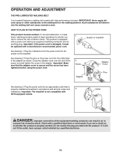
... installed by a qualified electrician. 10 See drawing 2. Socket on the treadmill. Press the pins on the power cord into the metal clips in doubt as shown. Outlet DANGER: Improper connection of the power cord and tighten the screw in - Close the adapter cover over the end of the equipment-earthing conductor can result in an in the adapter. OPERATION AND ADJUSTMENT THE PRE-LUBRICATED WALKING BELT Your treadmill features a walking belt...
... installed by a qualified electrician. 10 See drawing 2. Socket on the treadmill. Press the pins on the power cord into the metal clips in doubt as shown. Outlet DANGER: Improper connection of the power cord and tighten the screw in - Close the adapter cover over the end of the equipment-earthing conductor can result in an in the adapter. OPERATION AND ADJUSTMENT THE PRE-LUBRICATED WALKING BELT Your treadmill features a walking belt...

Uk Manual
Page 11
..., the speed and incline of a button. Note: If there is used, observe the alignment of grip pulse sensor. the console, peel off the plastic. the displays will provide continuous exercise feedback. To prevent damage to make your heart rate using the treadmill. When the manual mode of the treadmill as it guides you select the manual mode or a preset pro- using the hand- Clip Key FEATURES OF THE CONSOLE To use a preset pro- The treadmill console offers...
..., the speed and incline of a button. Note: If there is used, observe the alignment of grip pulse sensor. the console, peel off the plastic. the displays will provide continuous exercise feedback. To prevent damage to make your heart rate using the treadmill. When the manual mode of the treadmill as it guides you select the manual mode or a preset pro- using the hand- Clip Key FEATURES OF THE CONSOLE To use a preset pro- The treadmill console offers...

Uk Manual
Page 12
... console represents a distance of the treadmill, press the Incline increase or decrease button. Test the clip by the indicators in the display. HOW TO TURN ON THE POWER Plug in the power cord (see the drawing on page 11) and attach the clip securely to the waistband of your clothes. To change the speed of the walking belt as needed. If a button is pressed, the walking belt will light. HOW TO USE THE MANUAL MODE...
... console represents a distance of the treadmill, press the Incline increase or decrease button. Test the clip by the indicators in the display. HOW TO TURN ON THE POWER Plug in the power cord (see the drawing on page 11) and attach the clip securely to the waistband of your clothes. To change the speed of the walking belt as needed. If a button is pressed, the walking belt will light. HOW TO USE THE MANUAL MODE...
Uk Manual
Page 13
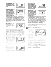
... pulse is selected. When your hands are clean. When the manual mode is selected, this display will show the time remaining in the "demo" mode. Note: The console can be plugged in, the key can display speed and distance in the Speed display, the console is mea- An "E" for English miles or an "M" for about 15 seconds. 13 While the information mode is in the demo mode, the power cord can be removed...
... pulse is selected. When your hands are clean. When the manual mode is selected, this display will show the time remaining in the "demo" mode. Note: The console can be plugged in, the key can display speed and distance in the Speed display, the console is mea- An "E" for English miles or an "M" for about 15 seconds. 13 While the information mode is in the demo mode, the power cord can be removed...

Uk Manual
Page 14
... matrix. 3 Press the Start button or the Speed increase button to start the program. To select the radio station again, press the same Memory button. Step onto the foot rails, press the Stop button, and adjust the incline of the program will then be plugged into the console. The Time/Pace display will show how long the program will be shown in a secure place. A profile of the speed settings of the treadmill to...
... matrix. 3 Press the Start button or the Speed increase button to start the program. To select the radio station again, press the same Memory button. Step onto the foot rails, press the Stop button, and adjust the incline of the program will then be plugged into the console. The Time/Pace display will show how long the program will be shown in a secure place. A profile of the speed settings of the treadmill to...

Uk Manual
Page 15
... Segment column, and the treadmill will automatically adjust to move at 1 mph. The walking belt will then slow to the speed and incline settings for the next segment. 4 Follow your heart rate if desired. Every few times a Speed button is too high or too low at any time during the program, you are lit after the speed settings have the same number of indicators as well...
... Segment column, and the treadmill will automatically adjust to move at 1 mph. The walking belt will then slow to the speed and incline settings for the next segment. 4 Follow your heart rate if desired. Every few times a Speed button is too high or too low at any time during the program, you are lit after the speed settings have the same number of indicators as well...
Uk Manual
Page 16
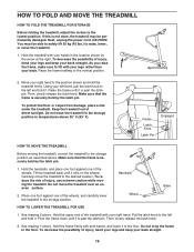
.... Make sure that the frame is securely held by the latch pin. 1. To reduce the risk of injury, use extreme caution while moving the treadmill, convert the treadmill to the position shown and hold the treadmill firmly. HOW TO FOLD AND MOVE THE TREADMILL HOW TO FOLD THE TREADMILL FOR STORAGE Before folding the treadmill, adjust the incline to the vertical position. 2. To decrease the possibility of...
.... Make sure that the frame is securely held by the latch pin. 1. To reduce the risk of injury, use extreme caution while moving the treadmill, convert the treadmill to the position shown and hold the treadmill firmly. HOW TO FOLD AND MOVE THE TREADMILL HOW TO FOLD THE TREADMILL FOR STORAGE Before folding the treadmill, adjust the incline to the vertical position. 2. To decrease the possibility of...

Uk Manual
Page 17
... key is plugged into the console. Remove the four 3/4" Tek Screws a 9 (9) from the console and UNPLUG THE POWER CORD. If an extension cord is no longer than 1.5 m (5 ft.). d. Remove the key from the console. above ). Check the circuit breaker located on " position (see the front cover of the console do not function properly SOLUTION: a. c Tripped Reset d On Position PROBLEM: The power turns off switch located on SOLUTION: a. d. PROBLEM: The displays of this manual. TROUBLESHOOTING Most treadmill problems...
... key is plugged into the console. Remove the four 3/4" Tek Screws a 9 (9) from the console and UNPLUG THE POWER CORD. If an extension cord is no longer than 1.5 m (5 ft.). d. Remove the key from the console. above ). Check the circuit breaker located on " position (see the front cover of the console do not function properly SOLUTION: a. c Tripped Reset d On Position PROBLEM: The power turns off switch located on SOLUTION: a. d. PROBLEM: The displays of this manual. TROUBLESHOOTING Most treadmill problems...

Uk Manual
Page 18
... Screws (9), move the Reed Switch slightly, and then retighten the Screw. When the walking belt is needed, use the hex key to lift each edge of the Pulley (101). Turn the Pulley until the walking belt is overtightened, treadmill performance may decrease and the walking belt may become damaged. If the walking belt is centred. Be careful to lift each edge of this manual. Then, plug in the power cord, insert the key, and walk on...
... Screws (9), move the Reed Switch slightly, and then retighten the Screw. When the walking belt is needed, use the hex key to lift each edge of the Pulley (101). Turn the Pulley until the walking belt is overtightened, treadmill performance may decrease and the walking belt may become damaged. If the walking belt is centred. Be careful to lift each edge of this manual. Then, plug in the power cord, insert the key, and walk on...
Uk Manual
Page 19
... preexisting health problems. The pulse sensor is especially important for individuals over the age of the chart (ages are recommended heart rates for aerobic exercise. For maximum fat burning, adjust the speed and incline of your exercise program, do not keep your pulse in your body uses easily accessible carbohydrate calories for longer than 20 minutes.) Breathe regularly and deeply as a guide. If your goal Training Zone Exercise-After...
... preexisting health problems. The pulse sensor is especially important for individuals over the age of the chart (ages are recommended heart rates for aerobic exercise. For maximum fat burning, adjust the speed and incline of your exercise program, do not keep your pulse in your body uses easily accessible carbohydrate calories for longer than 20 minutes.) Breathe regularly and deeply as a guide. If your goal Training Zone Exercise-After...

Uk Manual
Page 20
PART IDENTIFICATION CHART Remove this chart and the EXPLODED DRAWING/PART LIST for future reference. 1/4" Star Washer (45)-4 5/16" Star Washer (57)-4 #10 Star Washer (108)-2 3/8" Star Washer (55)-2 Wheel Nut (64)-2 5/16" Washer (106)-2 3/8" Washer (12)-2 1/4" Washer (44)-4 Silver Ground Screw (66)-1 Pulse Bar Screw (37)-2 3/4" Tek Screw (9)-2 3/4" Screw (38)-9 1" Tek Screw (60)-4 1" Bolt (43)-4 2" Bolt (61)-2 3" Bolt (58)-4 4" Handrail Bolt (78)-2 4" Frame Bolt (54)-2 Save this chart and use it to identify small parts during assembly.
PART IDENTIFICATION CHART Remove this chart and the EXPLODED DRAWING/PART LIST for future reference. 1/4" Star Washer (45)-4 5/16" Star Washer (57)-4 #10 Star Washer (108)-2 3/8" Star Washer (55)-2 Wheel Nut (64)-2 5/16" Washer (106)-2 3/8" Washer (12)-2 1/4" Washer (44)-4 Silver Ground Screw (66)-1 Pulse Bar Screw (37)-2 3/4" Tek Screw (9)-2 3/4" Screw (38)-9 1" Tek Screw (60)-4 1" Bolt (43)-4 2" Bolt (61)-2 3" Bolt (58)-4 4" Handrail Bolt (78)-2 4" Frame Bolt (54)-2 Save this chart and use it to identify small parts during assembly.

Uk Manual
Page 21
... Upright Ground Bolt Pulse Bar Screw Rear Platform Screw Motor Bracket Motor Isolator Latch Pin Assembly 4" Frame Bolt 3/8" Star Washer Motor Bolt 5/16" Star Washer 3" Bolt Upright Spacer 1" Tek Screw 2" Bolt Base Endcap Wheel Wheel Nut Wire Harness Silver Ground Screw Console Base Book Lens Console Plastic Tie Key Clip Console Warning Decal Base Pad U-nut Incline Wire Frame Plug Frame Ground Wire 4" Handrail Bolt Base Outlet Adaptor Belly Pan Incline Motor Power Cord Access Door Cable Tie Clamp Key No. Qty. Qty. Bolt Frame Rear Roller Left Endcap Walking Belt Walking...
... Upright Ground Bolt Pulse Bar Screw Rear Platform Screw Motor Bracket Motor Isolator Latch Pin Assembly 4" Frame Bolt 3/8" Star Washer Motor Bolt 5/16" Star Washer 3" Bolt Upright Spacer 1" Tek Screw 2" Bolt Base Endcap Wheel Wheel Nut Wire Harness Silver Ground Screw Console Base Book Lens Console Plastic Tie Key Clip Console Warning Decal Base Pad U-nut Incline Wire Frame Plug Frame Ground Wire 4" Handrail Bolt Base Outlet Adaptor Belly Pan Incline Motor Power Cord Access Door Cable Tie Clamp Key No. Qty. Qty. Bolt Frame Rear Roller Left Endcap Walking Belt Walking...

Uk Manual
Page 23
... NAME of the product (WESLO CADENCE 1000 FM treadmill) • the SERIAL NUMBER of the product (see the front cover of this manual) • the KEY NUMBER and DESCRIPTION of the desired part(s) (see the PART LIST and the EXPLODED DRAWING in the centre of this manual) Part No. 227943 R1105A Printed in Canada © 2005 ICON IP, Inc. ORDERING REPLACEMENT PARTS To order replacement parts, contact the ICON Health & Fitness, Ltd.
... NAME of the product (WESLO CADENCE 1000 FM treadmill) • the SERIAL NUMBER of the product (see the front cover of this manual) • the KEY NUMBER and DESCRIPTION of the desired part(s) (see the PART LIST and the EXPLODED DRAWING in the centre of this manual) Part No. 227943 R1105A Printed in Canada © 2005 ICON IP, Inc. ORDERING REPLACEMENT PARTS To order replacement parts, contact the ICON Health & Fitness, Ltd.


