
Owners Manual
Page 1
Model No. TL10.0i aliDE ilntaTM POWER INCLINE G • Assembly Warranty Operation and Adjustments Exercise Guidelines Maintenance and Storage Part Ordering Information OWNER'S MANUAL t4 • , .., , ' ' 1• '.rt !' ,Z I, N.... 1 i -i,i •"•,? 5 7 fi RS vvesloinc- Part No. 046324 11/89 A Division ofWeider Health and Fitness 'Patent Pending CAUTION: Read all Instructions carefully before using this Owner's Manual for reference. Retain this product.
Model No. TL10.0i aliDE ilntaTM POWER INCLINE G • Assembly Warranty Operation and Adjustments Exercise Guidelines Maintenance and Storage Part Ordering Information OWNER'S MANUAL t4 • , .., , ' ' 1• '.rt !' ,Z I, N.... 1 i -i,i •"•,? 5 7 fi RS vvesloinc- Part No. 046324 11/89 A Division ofWeider Health and Fitness 'Patent Pending CAUTION: Read all Instructions carefully before using this Owner's Manual for reference. Retain this product.
Owners Manual
Page 2
... made must be obtained by a Weslo authorized service center or for products used for individuals over the age of its authorized service centers with pre-existing health problems. Read all freight and other warranty beyond that specifically set forth above is limited to be received by Weslo at one of 35 or persons with all instructions before using. SOME STATES DO NOT ALLOW...
... made must be obtained by a Weslo authorized service center or for products used for individuals over the age of its authorized service centers with pre-existing health problems. Read all freight and other warranty beyond that specifically set forth above is limited to be received by Weslo at one of 35 or persons with all instructions before using. SOME STATES DO NOT ALLOW...

Owners Manual
Page 3
CADENCE1O.O1 Warranty 2 Safety Precautions 3 Before You Begin 4 Assembly 5 Operation and Adjustment 6 Maintenance and Storage 7 Conditioning Guidelines 8 Part List 10 Exploded Drawing 11 Part Ordering Information 12 IMPORTANT SAFETY PRECAUTIONS WARNING: To reduce the risk of six to ten feet in length with a three-wire conductor. 3. Plug the power cord directly into any object into a grounded circuit carrying 12 or more amps. Never start the treadmill while you...
CADENCE1O.O1 Warranty 2 Safety Precautions 3 Before You Begin 4 Assembly 5 Operation and Adjustment 6 Maintenance and Storage 7 Conditioning Guidelines 8 Part List 10 Exploded Drawing 11 Part Ordering Information 12 IMPORTANT SAFETY PRECAUTIONS WARNING: To reduce the risk of six to ten feet in length with a three-wire conductor. 3. Plug the power cord directly into any object into a grounded circuit carrying 12 or more amps. Never start the treadmill while you...
Owners Manual
Page 4
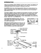
This manual is truly a state-of-the-art treadmill, offering many exclusive features for purchasing a Weslo CADENCE 10.0i Power Incline Treadmill. Mountain Time. If possible, place your telephone near the treadmill for easy reference. Incline Indicator Console Handrail Ear Clip Handrail Upright Power Incline Control Speed Control Knob Safety Switch Electronic Monitor Front Circuit Breaker Motor Hood Right Side Frame Grip Tape Incline Leg Walking Belt Front Wheels Power Cord Left Side Belt Adjustment Bolt Back 4 Walking Platform Write the serial number in the...
This manual is truly a state-of-the-art treadmill, offering many exclusive features for purchasing a Weslo CADENCE 10.0i Power Incline Treadmill. Mountain Time. If possible, place your telephone near the treadmill for easy reference. Incline Indicator Console Handrail Ear Clip Handrail Upright Power Incline Control Speed Control Knob Safety Switch Electronic Monitor Front Circuit Breaker Motor Hood Right Side Frame Grip Tape Incline Leg Walking Belt Front Wheels Power Cord Left Side Belt Adjustment Bolt Back 4 Walking Platform Write the serial number in the...
Owners Manual
Page 5
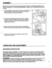
... ADJUSTMENT GROUNDING INSTRUCTIONS This product must be plugged into the back of the Upright Knob (29). The plug must be completed using the tool provided. 1. Make sure that all parts are tightened securely before operating the treadmill. Plug the Sensor Wire (76) into an appropriate outlet that is properly installed and grounded in doubt as to the vertical position and insert the Knob into the Console (10). ASSEMBLY...
... ADJUSTMENT GROUNDING INSTRUCTIONS This product must be plugged into the back of the Upright Knob (29). The plug must be completed using the tool provided. 1. Make sure that all parts are tightened securely before operating the treadmill. Plug the Sensor Wire (76) into an appropriate outlet that is properly installed and grounded in doubt as to the vertical position and insert the Knob into the Console (10). ASSEMBLY...
Owners Manual
Page 6
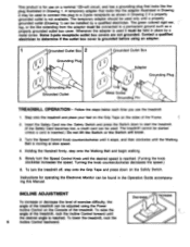
... Guide accompanying this plug to determine if the outlet box cover is grounded before using the Power Incline Control on the Safety Switch. Turn the Speed Control Knob counterclockwise until it must be used it stops, and then clockwise until the desired speed is reached. (Turning the knob clockwise increases the speed. Whenever the adapter is used . Slowly turn the treadmill off, step onto the Grip Tape and press down to connect this Manual. To lower the treadmill...
... Guide accompanying this plug to determine if the outlet box cover is grounded before using the Power Incline Control on the Safety Switch. Turn the Speed Control Knob counterclockwise until it must be used it stops, and then clockwise until the desired speed is reached. (Turning the knob clockwise increases the speed. Whenever the adapter is used . Slowly turn the treadmill off, step onto the Grip Tape and press down to connect this Manual. To lower the treadmill...
Owners Manual
Page 7
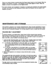
MAINTENANCE AND STORAGE This treadmill is designed to be adjusted, if necessary, by lowering the treadmill to the lowest degree of incline, and turning the small Adjustment Screw above the Power Incline Control on the treadmill for 3-4 minutes to ensure that they are tightened securely. Locate the Belt Adjustment Bolts and the Allen Wrench Caution: Keep your hands away from the moving Walking Belt or serious injury could result. 2. e 2B If the walking belt slips during...
MAINTENANCE AND STORAGE This treadmill is designed to be adjusted, if necessary, by lowering the treadmill to the lowest degree of incline, and turning the small Adjustment Screw above the Power Incline Control on the treadmill for 3-4 minutes to ensure that they are tightened securely. Locate the Belt Adjustment Bolts and the Allen Wrench Caution: Keep your hands away from the moving Walking Belt or serious injury could result. 2. e 2B If the walking belt slips during...

Owners Manual
Page 8
... lubricant is your personal fitness program. EXERCISE INTENSITY To maximize health benefits from the Electronic Monitor when storing the treadmill for extended periods of use or whenever a decrease in performance is very important to the area indicated in the drawing. For effective aerobic exercise the heart rate must exceed mild demands while falling short of the Walking Platform. CIRCUIT BREAKER If the treadmill stops...
... lubricant is your personal fitness program. EXERCISE INTENSITY To maximize health benefits from the Electronic Monitor when storing the treadmill for extended periods of use or whenever a decrease in performance is very important to the area indicated in the drawing. For effective aerobic exercise the heart rate must exceed mild demands while falling short of the Walking Platform. CIRCUIT BREAKER If the treadmill stops...
Owners Manual
Page 9
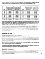
... your heart rate is too high, reduce your workout and should not be done by consulting the table below your Training Zone, increase your heart rate using the electronic monitor (see the ELECTRONIC MONITOR OPERATION GUIDE). At rest Warming up 3. You can determine your Training Zone by stretching and light calisthenics for 5-10 minutes prior to a successful program is REGULAR EXERCISE. 9 Press the "START/STOP" key and exercise at...
... your heart rate is too high, reduce your workout and should not be done by consulting the table below your Training Zone, increase your heart rate using the electronic monitor (see the ELECTRONIC MONITOR OPERATION GUIDE). At rest Warming up 3. You can determine your Training Zone by stretching and light calisthenics for 5-10 minutes prior to a successful program is REGULAR EXERCISE. 9 Press the "START/STOP" key and exercise at...
Owners Manual
Page 10
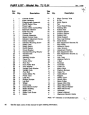
... 1 Upright Knob 30 1 Pivot Bolt 31 1 Incline Motor Pin 32 1 Power Cord 33 8 Lock Nut 34 2 Rubber Bumper 35 4 Leg Bolt 36 2 Wheel 37 1 Incline Leg 38 6 Hood Mount Anchor 39 4 Roller Bushing 40 2 Roller Lock 41 4 Roller Lock Screw 42 1 Motor 43 1 Motor Connect Wire 44 2 E-Clip 45 2 Motor Spacer 46 1 Fan 47 1 Front Roller/Pulley 48 1 Walking Belt 49 4 Rubber Pad 50 4 Support Spacer 51 6 Support Washer 52 6 Support Bolt 53 2 Wood Support 54 2 Rear Leg Endcap 55 15 Small Screw 56 1 Belt Adjustment...
... 1 Upright Knob 30 1 Pivot Bolt 31 1 Incline Motor Pin 32 1 Power Cord 33 8 Lock Nut 34 2 Rubber Bumper 35 4 Leg Bolt 36 2 Wheel 37 1 Incline Leg 38 6 Hood Mount Anchor 39 4 Roller Bushing 40 2 Roller Lock 41 4 Roller Lock Screw 42 1 Motor 43 1 Motor Connect Wire 44 2 E-Clip 45 2 Motor Spacer 46 1 Fan 47 1 Front Roller/Pulley 48 1 Walking Belt 49 4 Rubber Pad 50 4 Support Spacer 51 6 Support Washer 52 6 Support Bolt 53 2 Wood Support 54 2 Rear Leg Endcap 55 15 Small Screw 56 1 Belt Adjustment...
Owners Manual
Page 11
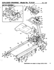
EXPLODED DRAWING - TL10.0i MOTOR ASSEMBLY 71 Zs48 2 18 81 82 55 79 55 72 73 47 74 7 78 5 I 75 /11 8 9 12 0 \ .00 13 7 6 5 4 2 • • t • Rev. 11/89 4 15 16 17 719 20 21 23 22 70 55 0' 24\ Nt 41 69 67 68 55 1 27 29 21143, le 66 40-V :--27 %•0--30 ( -31 65 64 47 46 2 45 411 40 48 39 32 33 34 35 63 62 6L1 s I 39 • 58 60 Pa1'`5\•9 \ 55 57 56 49 49 50 O 51 52 33 37 36 35 • 50 • 53 51 IN . 54 52 55 *Specifications are subject to change without notice. 11 Model No.
EXPLODED DRAWING - TL10.0i MOTOR ASSEMBLY 71 Zs48 2 18 81 82 55 79 55 72 73 47 74 7 78 5 I 75 /11 8 9 12 0 \ .00 13 7 6 5 4 2 • • t • Rev. 11/89 4 15 16 17 719 20 21 23 22 70 55 0' 24\ Nt 41 69 67 68 55 1 27 29 21143, le 66 40-V :--27 %•0--30 ( -31 65 64 47 46 2 45 411 40 48 39 32 33 34 35 63 62 6L1 s I 39 • 58 60 Pa1'`5\•9 \ 55 57 56 49 49 50 O 51 52 33 37 36 35 • 50 • 53 51 IN . 54 52 55 *Specifications are subject to change without notice. 11 Model No.
Owners Manual
Page 12
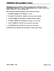
... SERIAL NUMBER OF THE PRODUCT (see page 4 of this manual. 6. The MODEL NUMBER OF THE PRODUCT ( TL10.0i ). 2. The PART NUMBER OF THE PRODUCT OWNER'S MANUAL (046324). 4. The KEY NUMBER OF THE PART from the part list in Canada at 1-800-99WESLO (999-3756), (in this manual. The NAME OF THE PRODUCT ( CADENCE 10.0i Power Incline Treadmill). 3. Part No. 046324 11/89 Printed in this manual). 5. If possible, place your telephone near the treadmill...
... SERIAL NUMBER OF THE PRODUCT (see page 4 of this manual. 6. The MODEL NUMBER OF THE PRODUCT ( TL10.0i ). 2. The PART NUMBER OF THE PRODUCT OWNER'S MANUAL (046324). 4. The KEY NUMBER OF THE PART from the part list in Canada at 1-800-99WESLO (999-3756), (in this manual. The NAME OF THE PRODUCT ( CADENCE 10.0i Power Incline Treadmill). 3. Part No. 046324 11/89 Printed in this manual). 5. If possible, place your telephone near the treadmill...


