
Uk Manual
Page 1
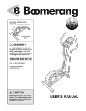
If you have questions, or if there are committed to providing complete customer satisfaction. Keep this equipment. WLEVEL28840 Serial No. Serial Number Decal QUESTIONS? As a manufacturer, we are missing or damaged parts, please call: 0034 91 661 02 10 Fax: 0034 91 661 98 32 E-mail: [email protected] CAUTION Read all precautions and instructions in this manual before using this manual for future reference. Model No. USERʼS MANUAL
If you have questions, or if there are committed to providing complete customer satisfaction. Keep this equipment. WLEVEL28840 Serial No. Serial Number Decal QUESTIONS? As a manufacturer, we are missing or damaged parts, please call: 0034 91 661 02 10 Fax: 0034 91 661 98 32 E-mail: [email protected] CAUTION Read all precautions and instructions in this manual before using this manual for future reference. Model No. USERʼS MANUAL
Uk Manual
Page 2
TABLE OF CONTENTS IMPORTANT PRECAUTIONS 3 BEFORE YOU BEGIN 4 ASSEMBLY 5 HOW TO USE THE ELLIPTICAL CROSSTRAINER 9 MAINTENANCE AND TROUBLESHOOTING 12 CONDITIONING GUIDELINES 13 PART LIST 14 EXPLODED DRAWING 15 HOW TO ORDER REPLACEMENT PARTS Back Cover 2
TABLE OF CONTENTS IMPORTANT PRECAUTIONS 3 BEFORE YOU BEGIN 4 ASSEMBLY 5 HOW TO USE THE ELLIPTICAL CROSSTRAINER 9 MAINTENANCE AND TROUBLESHOOTING 12 CONDITIONING GUIDELINES 13 PART LIST 14 EXPLODED DRAWING 15 HOW TO ORDER REPLACEMENT PARTS Back Cover 2
Uk Manual
Page 3
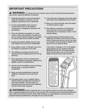
... the owner to ensure that the text on a level surface, with pre-existing health prob- The pulse sensor is intended only as described. 2. lems. Read all instructions before using . Use the elliptical crosstrainer only as an exercise aid in determining heart rate trends in the location shown below. Always hold the handlebars when mounting, dismounting, or using the elliptical crosstrainer. ICON assumes no responsibility for home use the elliptical crosstrainer in...
... the owner to ensure that the text on a level surface, with pre-existing health prob- The pulse sensor is intended only as described. 2. lems. Read all instructions before using . Use the elliptical crosstrainer only as an exercise aid in determining heart rate trends in the location shown below. Always hold the handlebars when mounting, dismounting, or using the elliptical crosstrainer. ICON assumes no responsibility for home use the elliptical crosstrainer in...
Uk Manual
Page 4
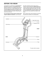
Handlebar Pulse Sensor Water Bottle Holder* Console Resistance Knob FRONT BACK Pedal Disk Pedal Arm Wheel Pedal *No water bottle is WLEVEL28840. BEFORE YOU BEGIN Congratulations for the location of this manual for selecting the new BOOMERANG 850 elliptical crosstrainer. For your exercise. The model number is included 4 If you get the most from your benefit, read this manual, please call our Customer Service Department at 0034 91 661 02 10...
Handlebar Pulse Sensor Water Bottle Holder* Console Resistance Knob FRONT BACK Pedal Disk Pedal Arm Wheel Pedal *No water bottle is WLEVEL28840. BEFORE YOU BEGIN Congratulations for the location of this manual for selecting the new BOOMERANG 850 elliptical crosstrainer. For your exercise. The model number is included 4 If you get the most from your benefit, read this manual, please call our Customer Service Department at 0034 91 661 02 10...
Uk Manual
Page 5
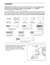
...)-6 M10 Washer (35)-2 M6 x 48mm Flat Head Screw (36)-4 M8 x 38mm Button Bolt (50)-4 M10 x 25mm Patch Screw (22)-2 M8 x 25mm Button Screw (45)-1 M8 x 19mm Button Screw (68)-6 M8 x 53mm Button Bolt (34)-4 Pedal Arm Bolt Set (40)-2 1. ASSEMBLY Assembly requires two persons. As you assemble the elliptical crosstrainer, use the drawings below each drawing refers to identify the small parts used in the parts bag, check to the Frame with two...
...)-6 M10 Washer (35)-2 M6 x 48mm Flat Head Screw (36)-4 M8 x 38mm Button Bolt (50)-4 M10 x 25mm Patch Screw (22)-2 M8 x 25mm Button Screw (45)-1 M8 x 19mm Button Screw (68)-6 M8 x 53mm Button Bolt (34)-4 Pedal Arm Bolt Set (40)-2 1. ASSEMBLY Assembly requires two persons. As you assemble the elliptical crosstrainer, use the drawings below each drawing refers to identify the small parts used in the parts bag, check to the Frame with two...
Uk Manual
Page 6
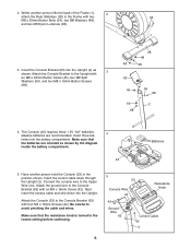
... Screws (42). Make sure that the batteries are recommended. Attach the Console Bracket to the lowest setting before continuing. 5 23 Console Wire 44 Resistance Knob 42 Ground Wire 63 Control Cable 42 2 6 alkaline batteries are oriented as 3 shown. Connect the console wire to avoid pinching the cable and wires. Insert the Console Bracket (63) into the battery compartment. Make sure that the resistance knob is turned to the Upright with two 34 M8 x 53mm Button Bolts...
... Screws (42). Make sure that the batteries are recommended. Attach the Console Bracket to the lowest setting before continuing. 5 23 Console Wire 44 Resistance Knob 42 Ground Wire 63 Control Cable 42 2 6 alkaline batteries are oriented as 3 shown. Connect the console wire to avoid pinching the cable and wires. Insert the Console Bracket (63) into the battery compartment. Make sure that the resistance knob is turned to the Upright with two 34 M8 x 53mm Button Bolts...

Uk Manual
Page 7
... step to the Handlebar Arm with a sticker. Attach the Upright with four M8 x 19mm Button Screws (68) and four M8 Split Washers (59). make sure that the Handlebar Arm is facing the Upright. Make sure that the wires and cables do not get pinched and damaged during this step. Firmly pull the control cable and slide it into the Frame (1). Do not tighten the Button Screws...
... step to the Handlebar Arm with a sticker. Attach the Upright with four M8 x 19mm Button Screws (68) and four M8 Split Washers (59). make sure that the Handlebar Arm is facing the Upright. Make sure that the wires and cables do not get pinched and damaged during this step. Firmly pull the control cable and slide it into the Frame (1). Do not tighten the Button Screws...
Uk Manual
Page 8
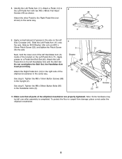
...). Next, hold the lower end of the left over after assembly is completed. Tighten the M8 x 38mm Button Bolts (50) in the Upright (2). Slide the Left Pedal Arm (11) onto the axle. Attach the Left Pedal Arm to the Right Pedal Arm (not shown) in the same way. Note: Some hardware may be left Handlebar Arm (5) inside of the elliptical crosstrainer are properly tightened. See step 5. Slide an...
...). Next, hold the lower end of the left over after assembly is completed. Tighten the M8 x 38mm Button Bolts (50) in the Upright (2). Slide the Left Pedal Arm (11) onto the axle. Attach the Left Pedal Arm to the Right Pedal Arm (not shown) in the same way. Note: Some hardware may be left Handlebar Arm (5) inside of the elliptical crosstrainer are properly tightened. See step 5. Slide an...
Uk Manual
Page 9
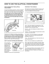
... knob counterclockwise. the pedals will display the following modes: Pedal Pedal Disk To dismount the elliptical crosstrainer, wait until the pedals come to a complete stop pedalling, the time will show both the speed mode and the distance mode, and the lower left section of the pedals with a continuous motion. Then, step off the highest pedal first. HOW TO ADJUST THE PEDALING RESISTANCE As you exercise, you exercise, the console will continue to -use the pulse sensor. Speed-This mode displays your heart rate...
... knob counterclockwise. the pedals will display the following modes: Pedal Pedal Disk To dismount the elliptical crosstrainer, wait until the pedals come to a complete stop pedalling, the time will show both the speed mode and the distance mode, and the lower left section of the pedals with a continuous motion. Then, step off the highest pedal first. HOW TO ADJUST THE PEDALING RESISTANCE As you exercise, you exercise, the console will continue to -use the pulse sensor. Speed-This mode displays your heart rate...
Uk Manual
Page 10
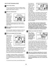
... contacts of the display will then show speed and distance in height. Note: If there are not pressed for about six seconds. HOW TO USE THE MANUAL MODE 1 Turn on the console, press the On/Reset button or begin pedalling. The upper section of the pulse sensor, peel off after a few minutes, the console will automatically turn on the console. If the pedals are not moved and the console buttons are thin...
... contacts of the display will then show speed and distance in height. Note: If there are not pressed for about six seconds. HOW TO USE THE MANUAL MODE 1 Turn on the console, press the On/Reset button or begin pedalling. The upper section of the pulse sensor, peel off after a few minutes, the console will automatically turn on the console. If the pedals are not moved and the console buttons are thin...
Uk Manual
Page 11
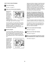
... PROGRAM 1 Turn on page 10. 5 Measure your heart rate if desired. See step 4 on the console. See step 6 on , the manual mode will be shown by turning the resistance knob. If you to show the time remaining in the program. If your pedalling pace is completed, the display will automatically turn off after the program is slower than the target pace settings, especially during the programs. For example, profile number...
... PROGRAM 1 Turn on page 10. 5 Measure your heart rate if desired. See step 4 on the console. See step 6 on , the manual mode will be shown by turning the resistance knob. If you to show the time remaining in the program. If your pedalling pace is completed, the display will automatically turn off after the program is slower than the target pace settings, especially during the programs. For example, profile number...
Uk Manual
Page 12
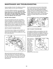
.... See the drawing below and locate the Reed Switch (53). MAINTENANCE AND TROUBLESHOOTING Inspect and tighten all parts of direct sunlight. BATTERY REPLACEMENT If the console display becomes dim, the batteries should be adjusted. To adjust the Drive Belt, you must remove the Left Pedal Arm (11) and the Left Side Shield (3). 56 42 3 40 11 35 42 22 42 Remove the Pedal Arm Bolt Set (40), the M10 x 25mm Patch Screw (22), and the M10...
.... See the drawing below and locate the Reed Switch (53). MAINTENANCE AND TROUBLESHOOTING Inspect and tighten all parts of direct sunlight. BATTERY REPLACEMENT If the console display becomes dim, the batteries should be adjusted. To adjust the Drive Belt, you must remove the Left Pedal Arm (11) and the Left Side Shield (3). 56 42 3 40 11 35 42 22 42 Remove the Pedal Arm Bolt Set (40), the M10 x 25mm Patch Screw (22), and the M10...
Uk Manual
Page 13
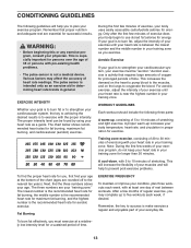
... exercise with pre-existing health problems. • The pulse sensor is to burn fat or to strengthen your exercise must exercise at a relatively low intensity level for longer than 20 minutes. For aerobic exercise, adjust the intensity of your exercise until your training zone for a sustained period of time. Training zone exercise, consisting of 20 to 30 minutes of exercising with your heart rate in your heart rate...
... exercise with pre-existing health problems. • The pulse sensor is to burn fat or to strengthen your exercise must exercise at a relatively low intensity level for longer than 20 minutes. For aerobic exercise, adjust the intensity of your exercise until your training zone for a sustained period of time. Training zone exercise, consisting of 20 to 30 minutes of exercising with your heart rate in your heart rate...
Uk Manual
Page 14
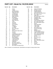
... Screw 37 2 Pedal Arm Bushing 38 10 M8 Nylon Locknut 39 2 Flywheel Washer 40 2 Pedal Arm Bolt Set 41 1 M8 x 22mm Flat Head Screw 42 24 M4 x 16mm Screw 44 1 Upper Wire 45 1 M8 x 25mm Button Screw 46 2 Handlebar Cap 47 2 Handlebar Spacer 48 4 M8 Washer 49 4 Small Handlebar Bushing 50 4 M8 x 38mm Button Bolt 51 8 M6 x 35mm Button Screw 52 1 Spring 53 1 Reed Switch/Wire 54 1 Cable Clamp 55 1 Lower Cable...
... Screw 37 2 Pedal Arm Bushing 38 10 M8 Nylon Locknut 39 2 Flywheel Washer 40 2 Pedal Arm Bolt Set 41 1 M8 x 22mm Flat Head Screw 42 24 M4 x 16mm Screw 44 1 Upper Wire 45 1 M8 x 25mm Button Screw 46 2 Handlebar Cap 47 2 Handlebar Spacer 48 4 M8 Washer 49 4 Small Handlebar Bushing 50 4 M8 x 38mm Button Bolt 51 8 M6 x 35mm Button Screw 52 1 Spring 53 1 Reed Switch/Wire 54 1 Cable Clamp 55 1 Lower Cable...
Uk Manual
Page 15
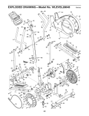
EXPLODED DRAWING-Model No. WLEVEL28840 R0604A 46 42 42 23 42 4 20 63 42 42 24 27 46 42 42 56 42 45 68 42 8 3 24 59 59 68 49 47 49 14 42 6 50 49 38 2 38 49 47 50 5 60 65 21 42 40 14 34 60 27 27 38 69 36 44 65 38 48 13 59 68 59 68 5 68 59 21 10 42 69 60 55 29 39 57 58 37 42 54 40 40 12 60 38 18 17 29 39 52 16 30 31 42 36 13 22 35 26 27 64 25 37 33 67 20 51 61 51 15 11 35 25 40 22 51 19 51 15 51 53 27 61 9 66 66 41 27 9 1 32 16 30 31 21 7 38 34 21 42 28 48 62 48 42 38 15
EXPLODED DRAWING-Model No. WLEVEL28840 R0604A 46 42 42 23 42 4 20 63 42 42 24 27 46 42 42 56 42 45 68 42 8 3 24 59 59 68 49 47 49 14 42 6 50 49 38 2 38 49 47 50 5 60 65 21 42 40 14 34 60 27 27 38 69 36 44 65 38 48 13 59 68 59 68 5 68 59 21 10 42 69 60 55 29 39 57 58 37 42 54 40 40 12 60 38 18 17 29 39 52 16 30 31 42 36 13 22 35 26 27 64 25 37 33 67 20 51 61 51 15 11 35 25 40 22 51 19 51 15 51 53 27 61 9 66 66 41 27 9 1 32 16 30 31 21 7 38 34 21 42 28 48 62 48 42 38 15
Uk Manual
Page 16
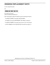
... the following information: • the MODEL NUMBER of the product (WLEVEL28840) • the NAME of the product (BOOMERANG™ 850 elliptical crosstrainer) • the SERIAL NUMBER of the product (see the front cover of this manual) • the KEY NUMBER and the DESCRIPTION of the part(s) (see page 14) Manufactured in China © 2004 ICON IP, Inc. Part No. 211891 R0604A Printed in China for ICON Health & Fitness, Inc.
... the following information: • the MODEL NUMBER of the product (WLEVEL28840) • the NAME of the product (BOOMERANG™ 850 elliptical crosstrainer) • the SERIAL NUMBER of the product (see the front cover of this manual) • the KEY NUMBER and the DESCRIPTION of the part(s) (see page 14) Manufactured in China © 2004 ICON IP, Inc. Part No. 211891 R0604A Printed in China for ICON Health & Fitness, Inc.


