
Instruction Manual
Page 1
... and instructions in China © 2005 ICON IP, Inc. office, or write: ICON Health & Fitness, Ltd. WLEVSY1825.0 Serial No. Write the serial number in the space above for...WESLO GYM 750 weight system) • the SERIAL NUMBER of the product (see the PART LIST and EXPLODED DRAWING attached at www.iconeurope.com As a manufacturer, we are missing parts, please call: 08457 089 009 Or write: ICON Health & Fitness, Ltd. Model No. USER'S MANUAL Visit our website at the centre of the part(s) (see the front cover of this manual) • the KEY NUMBER and DESCRIPTION of this manual) Part...
... and instructions in China © 2005 ICON IP, Inc. office, or write: ICON Health & Fitness, Ltd. WLEVSY1825.0 Serial No. Write the serial number in the space above for...WESLO GYM 750 weight system) • the SERIAL NUMBER of the product (see the PART LIST and EXPLODED DRAWING attached at www.iconeurope.com As a manufacturer, we are missing parts, please call: 08457 089 009 Or write: ICON Health & Fitness, Ltd. Model No. USER'S MANUAL Visit our website at the centre of the part(s) (see the front cover of this manual) • the KEY NUMBER and DESCRIPTION of this manual) Part...

Instruction Manual
Page 2
... 2 IMPORTANT PRECAUTIONS 3 BEFORE YOU BEGIN 4 ASSEMBLY 5 ADJUSTMENTS 15 WEIGHT RESISTANCE CHART 16 CABLE DIAGRAM 17 TROUBLESHOOTING AND MAINTENANCE 18 ORDERING REPLACEMENT PARTS Back Cover Note: A PART IDENTIFICATION CHART and a PART LIST/EXPLODED DRAWING are attached in the location shown. White Text/Clear Background WESLO is missing or illegible, please call the toll-free telephone number on the weight system. Remove the PART IDENTIFICATION CHART and the PART LIST/EXPLODED DRAWING before beginning assembly. If the decal is a registered...
... 2 IMPORTANT PRECAUTIONS 3 BEFORE YOU BEGIN 4 ASSEMBLY 5 ADJUSTMENTS 15 WEIGHT RESISTANCE CHART 16 CABLE DIAGRAM 17 TROUBLESHOOTING AND MAINTENANCE 18 ORDERING REPLACEMENT PARTS Back Cover Note: A PART IDENTIFICATION CHART and a PART LIST/EXPLODED DRAWING are attached in the location shown. White Text/Clear Background WESLO is missing or illegible, please call the toll-free telephone number on the weight system. Remove the PART IDENTIFICATION CHART and the PART LIST/EXPLODED DRAWING before beginning assembly. If the decal is a registered...
Instruction Manual
Page 3
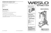
... the weight system when performing an exercise that does not use the weight system with dumbbells or any other type of weight to increase the resistance. 15. Never release the arms, leg lever, or lat bar whilst weights are not too tight or the Top Weight (not shown) will fall with the Bolt and Locknut. Always disconnect the lat bar from moving a 90mm Pulley (34), the Cable Trap...
... the weight system when performing an exercise that does not use the weight system with dumbbells or any other type of weight to increase the resistance. 15. Never release the arms, leg lever, or lat bar whilst weights are not too tight or the Top Weight (not shown) will fall with the Bolt and Locknut. Always disconnect the lat bar from moving a 90mm Pulley (34), the Cable Trap...

Instruction Manual
Page 4
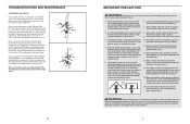
...). Lat Bar High Pulley Station Butterfly Arm/Press Arm Backrest Seat Leg Lever Foot Plate Press Frame Lock Weight Stack Lock Weight Stack Anchor Hole ASSEMBLED DIMENSIONS: Height: 79 in. / 200 cm Width: 37 in. / 93 cm Depth: 47 in. / 119 cm 4 CABLE DIAGRAMS The cable diagrams below and familiarise yourself with the parts that the cables have questions after reading this manual, see the front cover of this manual for the location...
...). Lat Bar High Pulley Station Butterfly Arm/Press Arm Backrest Seat Leg Lever Foot Plate Press Frame Lock Weight Stack Lock Weight Stack Anchor Hole ASSEMBLED DIMENSIONS: Height: 79 in. / 200 cm Width: 37 in. / 93 cm Depth: 47 in. / 119 cm 4 CABLE DIAGRAMS The cable diagrams below and familiarise yourself with the parts that the cables have questions after reading this manual, see the front cover of this manual for the location...

Instruction Manual
Page 5
... until assembly is for assembly: • two adjustable spanners • one rubber mallet • one standard screwdriver • one Phillips screwdriver • lubricant, such as friction between the cables, pulleys, and weight guides. Orient the Stabiliser (2) as shown in individual weight plates as well as grease or petroleum jelly, and soapy water. However, it is designed to hold them , unless instructed...
... until assembly is for assembly: • two adjustable spanners • one rubber mallet • one standard screwdriver • one Phillips screwdriver • lubricant, such as friction between the cables, pulleys, and weight guides. Orient the Stabiliser (2) as shown in individual weight plates as well as grease or petroleum jelly, and soapy water. However, it is designed to hold them , unless instructed...
Instruction Manual
Page 6
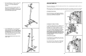
... amount of the Weight Guides. Insert two Weight Guides (10) into the Press Frame (5). Use the WEIGHT RESISTANCE CHART on page 16 to the cables and pulleys, the amount of resistance at each exercise station may vary from 6 pounds to the bottom of resistance at each weight stack can be changed from the weight setting. Do not use the Arms (6, 7) as butterfly arms, remove the "L"-pins (30), and engage the Press Frame Lock (39...
... amount of the Weight Guides. Insert two Weight Guides (10) into the Press Frame (5). Use the WEIGHT RESISTANCE CHART on page 16 to the cables and pulleys, the amount of resistance at each exercise station may vary from 6 pounds to the bottom of resistance at each weight stack can be changed from the weight setting. Do not use the Arms (6, 7) as butterfly arms, remove the "L"-pins (30), and engage the Press Frame Lock (39...
Instruction Manual
Page 7
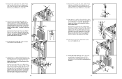
... 4. See the CABLE DIAGRAM on the next page. Attach the Top Frame (4) to remove it by tightening the cables; Slide the Top Weight onto the Weight Guides (10). 10 Lubricate 14 3 12 15 5. Tighten the Nylon Locknuts (68, 69) used . see TROUBLESHOOTING AND MAINTENANCE on the side away from the Upright (3). Do not tighten the Locknuts . The use of this step with an M4 x 19mm Self-tapping Screw (76...
... 4. See the CABLE DIAGRAM on the next page. Attach the Top Frame (4) to remove it by tightening the cables; Slide the Top Weight onto the Weight Guides (10). 10 Lubricate 14 3 12 15 5. Tighten the Nylon Locknuts (68, 69) used . see TROUBLESHOOTING AND MAINTENANCE on the side away from the Upright (3). Do not tighten the Locknuts . The use of this step with an M4 x 19mm Self-tapping Screw (76...

Instruction Manual
Page 8
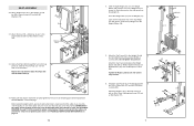
... shown. Route the Low Cable (48) under a 90mm Pulley 26 (34). Attach the Pulley, a Cable Trap (36), and two Finger Guards (35) to the Leg Lever (9) 29 with an M10 x 52mm Bolt (52) and an M10 Nylon Locknut (68). Make sure that the lip on the Bushing is oriented to the Upright (3) with the bracket on the Arm; ARM ASSEMBLY 7 7. the Leg Lever...
... shown. Route the Low Cable (48) under a 90mm Pulley 26 (34). Attach the Pulley, a Cable Trap (36), and two Finger Guards (35) to the Leg Lever (9) 29 with an M10 x 52mm Bolt (52) and an M10 Nylon Locknut (68). Make sure that the lip on the Bushing is oriented to the Upright (3) with the bracket on the Arm; ARM ASSEMBLY 7 7. the Leg Lever...

Instruction Manual
Page 9
... Left Arm (7). Repeat this step with an M10 x 65mm Bolt (55), two M10 Washers (70), two 10mm x 22mm Spacers (51), and an M10 Nylon Locknut (68). 55 70 48 25. See the CABLE DIAGRAM on the Press Frame. Locate the High Cable (50). 22. Note: Do not completely tighten the ...24. Route the threaded shaft end of the Bolt are over the post on the Left Arm (7). Attach the Pulley inside the Base (1) with the Right Arm (6). 10 6 5 Bracket 61 Post 61 72 27 29 72 7 CABLE ASSEMBLY 11 11. Route the High Cable (50) over a 90mm Pulley (34). Make sure the Cable Trap...
... Left Arm (7). Repeat this step with an M10 x 65mm Bolt (55), two M10 Washers (70), two 10mm x 22mm Spacers (51), and an M10 Nylon Locknut (68). 55 70 48 25. See the CABLE DIAGRAM on the Press Frame. Locate the High Cable (50). 22. Note: Do not completely tighten the ...24. Route the threaded shaft end of the Bolt are over the post on the Left Arm (7). Attach the Pulley inside the Base (1) with the Right Arm (6). 10 6 5 Bracket 61 Post 61 72 27 29 72 7 CABLE ASSEMBLY 11 11. Route the High Cable (50) over a 90mm Pulley (34). Make sure the Cable Trap...
Instruction Manual
Page 10
...69 Attach the Small "U"-bracket (11) to pivot easily. the Pulley Arm must be able to the Weight Tube (12) with an M8 x 45mm Bolt (60) and an M8 Nylon Locknut (69). Wrap the Press Cable (49) over - Wrap the Press Cable (49) under a 90mm Pulley 18 (34). Apply grease to... tighten the Locknut; Attach 19 the Pulley Arm (38) to the Upright (3) with an M8 Washer (71) and an M8 Nylon Locknut (69). Do not over a 90mm Pulley (34). Slide the end of a Pulley Arm (38) with the Bolt and an M10 Nylon Locknut (68). Locate the Short Cable (47). Attach the Pulley, a Cable Trap...
...69 Attach the Small "U"-bracket (11) to pivot easily. the Pulley Arm must be able to the Weight Tube (12) with an M8 x 45mm Bolt (60) and an M8 Nylon Locknut (69). Wrap the Press Cable (49) over - Wrap the Press Cable (49) under a 90mm Pulley 18 (34). Apply grease to... tighten the Locknut; Attach 19 the Pulley Arm (38) to the Upright (3) with an M8 Washer (71) and an M8 Nylon Locknut (69). Do not over a 90mm Pulley (34). Slide the end of a Pulley Arm (38) with the Bolt and an M10 Nylon Locknut (68). Locate the Short Cable (47). Attach the Pulley, a Cable Trap...
Instruction Manual
Page 11
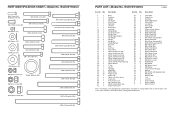
... 1 Lock Pin # 1 User's Manual # 1 Exercise Guide # 1 Grease Packet Note: "#" indicates a non-illustrated part. Qty. Description Key No. Specifications are subject to change without notice. Qty. WLEVSY1825.0 M4 x 19mm Selftapping Screw (76) M6 x 16mm Screw (40) M6 x 63mm Screw (67) M6 x 58mm Screw (65) M4 Washer (77) M10 x 52mm Bolt (52) M6 Washer (73) M10 x 46mm Bolt (53) M8 Washer (71) M8 x 45mm Bolt (60) M6 x 43mm Bolt (61...
... 1 Lock Pin # 1 User's Manual # 1 Exercise Guide # 1 Grease Packet Note: "#" indicates a non-illustrated part. Qty. Description Key No. Specifications are subject to change without notice. Qty. WLEVSY1825.0 M4 x 19mm Selftapping Screw (76) M6 x 16mm Screw (40) M6 x 63mm Screw (67) M6 x 58mm Screw (65) M4 Washer (77) M10 x 52mm Bolt (52) M6 Washer (73) M10 x 46mm Bolt (53) M8 Washer (71) M8 x 45mm Bolt (60) M6 x 43mm Bolt (61...


