
English Manual
Page 11
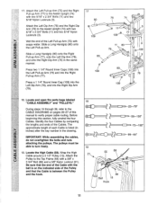
..." and "PULLEYS." Before beginning this manual to the Assist Upright (74) with im soapy water. Wet the end of this section, fully unwind the four Cables. Slide a Long Handgrip (80) onto the Right Pull-up Arm (75) with two 5/16" x 2 3/4" Bolts (11) and two 5/16" Nylon Locknuts .... 17. Attach the Left Dip Arm (78) and the Right Dip Arm (79) to verify proper cable routing. IMPORTANT: While assembling the cables, do not overtighten the bolts and nuts attaching the pulleys. Locate the High Cable (58). Attach the Pulley to turn freely. 19. The approximate length of the...
..." and "PULLEYS." Before beginning this manual to the Assist Upright (74) with im soapy water. Wet the end of this section, fully unwind the four Cables. Slide a Long Handgrip (80) onto the Right Pull-up Arm (75) with two 5/16" x 2 3/4" Bolts (11) and two 5/16" Nylon Locknuts .... 17. Attach the Left Dip Arm (78) and the Right Dip Arm (79) to verify proper cable routing. IMPORTANT: While assembling the cables, do not overtighten the bolts and nuts attaching the pulleys. Locate the High Cable (58). Attach the Pulley to turn freely. 19. The approximate length of the...
English Manual
Page 12
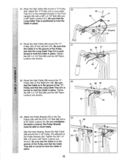
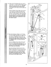
... place. Tighten the 3/8" x 2 1/2" Bolt (86) and the 3/8" Nylon Locknut (not shown). 31 86 50 58 • 48 \\ 23. Route the High Cable (58) around the "V"Pulley (50) on the Right Arm (48). Tighten the 3/8" x 2 1/2" Bolt (86) and the 3/8" Nylon Locknut (not shown). 86 , 31 58... in place. the Pulley Bracket \\/ must be able to the Top Frame (55) with a 3/8" x 2 1/2" Bolt (86) and a 3/8" Nylon Locknut (21). Route the High Cable (58) around the "V"Pulley (50) on the Front Upright (42) with the 5/16" x 5" Bolt (68) and a 23 08 5/16" Nylon Locknut (3). Attach...
... place. Tighten the 3/8" x 2 1/2" Bolt (86) and the 3/8" Nylon Locknut (not shown). 31 86 50 58 • 48 \\ 23. Route the High Cable (58) around the "V"Pulley (50) on the Right Arm (48). Tighten the 3/8" x 2 1/2" Bolt (86) and the 3/8" Nylon Locknut (not shown). 86 , 31 58... in place. the Pulley Bracket \\/ must be able to the Top Frame (55) with a 3/8" x 2 1/2" Bolt (86) and a 3/8" Nylon Locknut (21). Route the High Cable (58) around the "V"Pulley (50) on the Front Upright (42) with the 5/16" x 5" Bolt (68) and a 23 08 5/16" Nylon Locknut (3). Attach...
English Manual
Page 13
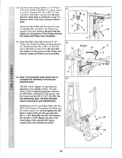
Note: This may come pre-assembled. Route the High Cable (58) through the Long "U"-Bracket (57) and the 3 1/2" Pulley (15) shown in the groove of several pre- 26 attached parts. Wrap the High Cable (58) around a 3 1/2" Pulley (15). a 57 12 25 55 57 Bracket 58 15 58 12 ...move smoothly. 25. Do not tighten the 3/8" Nylon Locknut (21) yet. The Bolt has been shown removed for shipping purposes. Attach a 3 1/2" Pulley (15) and a Cable Trap (66) to the upper hole in the groove of the 3 1/2" Low Pulley (102) for part identification. Reattach the 3 1/2" Low Pulley (102), with a 3/8"...
Note: This may come pre-assembled. Route the High Cable (58) through the Long "U"-Bracket (57) and the 3 1/2" Pulley (15) shown in the groove of several pre- 26 attached parts. Wrap the High Cable (58) around a 3 1/2" Pulley (15). a 57 12 25 55 57 Bracket 58 15 58 12 ...move smoothly. 25. Do not tighten the 3/8" Nylon Locknut (21) yet. The Bolt has been shown removed for shipping purposes. Attach a 3 1/2" Pulley (15) and a Cable Trap (66) to the upper hole in the groove of the 3 1/2" Low Pulley (102) for part identification. Reattach the 3 1/2" Low Pulley (102), with a 3/8"...

English Manual
Page 14
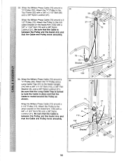
...Locknut (21) and the 3/8" x 3 3/4" Bolt (not shown). 1) 0 t ® 6 Crossbar 21 102 23 Ball 17 28. Route the Low Cable (23) around the 3 1/2" Pulley (15) attached to hold the Cable in the 29 Press Frame (17). Tighten the 3/8" Nylon Locknut (21) and the 3/8" x 3 3/4" Bolt (88). ..--. 23 15 88... 66 42 Inset shows view from other side 14 Be sure that the Cable is turned to the upper hole in place and that the Cable Trap (66) is routed around the Pulley as shown. Tighten the 3/8" Nylon Locknut (21) and the 3/8" x 3 1/2" Bolt (not...
...Locknut (21) and the 3/8" x 3 3/4" Bolt (not shown). 1) 0 t ® 6 Crossbar 21 102 23 Ball 17 28. Route the Low Cable (23) around the 3 1/2" Pulley (15) attached to hold the Cable in the 29 Press Frame (17). Tighten the 3/8" Nylon Locknut (21) and the 3/8" x 3 3/4" Bolt (88). ..--. 23 15 88... 66 42 Inset shows view from other side 14 Be sure that the Cable is turned to the upper hole in place and that the Cable Trap (66) is routed around the Pulley as shown. Tighten the 3/8" Nylon Locknut (21) and the 3/8" x 3 1/2" Bolt (not...
English Manual
Page 16
... Locknut (21). Attach the Pulley to hold the Cable in place and that the Long Cable Trap is routed around the Pulley as shown. Wrap the Military Press Cable (72) around a 3 1/2" Pulley (15). 34. Wrap the Military Press Cable (72) around a 34 "V"-Pulley (50). Wrap the Military Press Cable (72) around a 3 1/2" Pulley (15). Be sure that...
... Locknut (21). Attach the Pulley to hold the Cable in place and that the Long Cable Trap is routed around the Pulley as shown. Wrap the Military Press Cable (72) around a 3 1/2" Pulley (15). 34. Wrap the Military Press Cable (72) around a 34 "V"-Pulley (50). Wrap the Military Press Cable (72) around a 3 1/2" Pulley (15). Be sure that...
English Manual
Page 17
... B. Slide the end of the Military Press Cable (72) onto the end of the Cable to hold the Cable in the groove of the Pulley and that the Cable Trap is inside the Long "U"-Bracket. (Note: This may come preassembled.) Route the Military Press Cable (72) through the indicated hole in a ... for the end of the 5/16" x 2 3/4 Bolt (11). Attach the Pulley and a Cable Trap (66) to the upper hole in the Pivot Arm (101). Wrap the Military Press Cable (72) around a 3 1/2" Pulley (15). Attach a 3 1/2" Pulley (15) and a Cable Trap (66) to the Pivot Arm (101) with a 3/8" x 2" Bolt (12) and ...
... B. Slide the end of the Military Press Cable (72) onto the end of the Cable to hold the Cable in the groove of the Pulley and that the Cable Trap is inside the Long "U"-Bracket. (Note: This may come preassembled.) Route the Military Press Cable (72) through the indicated hole in a ... for the end of the 5/16" x 2 3/4 Bolt (11). Attach the Pulley and a Cable Trap (66) to the upper hole in the Pivot Arm (101). Wrap the Military Press Cable (72) around a 3 1/2" Pulley (15). Attach a 3 1/2" Pulley (15) and a Cable Trap (66) to the Pivot Arm (101) with a 3/8" x 2" Bolt (12) and ...
English Manual
Page 21
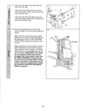
...3/4" Round Inner Caps (34) into each cable a few times to the home gym system as 48 shown. Slide a Foam Pad (30) onto each end of this manual for proper cable routing. Remove the backing from the PRO 9645 decal and apply it by tightening the cables. If there is used. If one of ...this manual. See the CABLE DIAGRAMS on page 25. 0 36 30 34 28 34 0 30 0 29 0 PRO 9645 lR ci) ----- 00 21 See TROUBLE...
...3/4" Round Inner Caps (34) into each cable a few times to the home gym system as 48 shown. Slide a Foam Pad (30) onto each end of this manual for proper cable routing. Remove the backing from the PRO 9645 decal and apply it by tightening the cables. If there is used. If one of ...this manual. See the CABLE DIAGRAMS on page 25. 0 36 30 34 28 34 0 30 0 29 0 PRO 9645 lR ci) ----- 00 21 See TROUBLE...
English Manual
Page 26
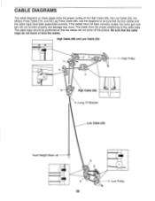
... gym system will not come off the pulleys. The insets show the proper routing of the cable traps. The cable traps should be sure that the cable traps do not touch or bind the cables. High Cable (58) and Low Cable (23) 2 3 :11 1 High Pulley 5 4 6 High Cable (58) 5-Long "U"-Bracket Low Cable (23) Front Weight Stack-8 4 0 3 2 1-Low Pulley 26
... gym system will not come off the pulleys. The insets show the proper routing of the cable traps. The cable traps should be sure that the cable traps do not touch or bind the cables. High Cable (58) and Low Cable (23) 2 3 :11 1 High Pulley 5 4 6 High Cable (58) 5-Long "U"-Bracket Low Cable (23) Front Weight Stack-8 4 0 3 2 1-Low Pulley 26


