
English Manual
Page 1
MST CAUTION Read all precautions and instructions in the space above for future reference. Write the serial number in this manual before using this manual for reference. As a manufacturer, we will provide immediate assistance, free of charge to providing complete customer satisfaction. The trained technicians on our customer hot line will guarantee complete satisfaction through direct assistance from our factory. Save this equipment. If you have questions, or if there are missing parts, we are committed to you. TO AVOID UNNECESSARY DELAYS, PLEASE CALL DIRECT...
MST CAUTION Read all precautions and instructions in the space above for future reference. Write the serial number in this manual before using this manual for reference. As a manufacturer, we will provide immediate assistance, free of charge to providing complete customer satisfaction. The trained technicians on our customer hot line will guarantee complete satisfaction through direct assistance from our factory. Save this equipment. If you have questions, or if there are missing parts, we are committed to you. TO AVOID UNNECESSARY DELAYS, PLEASE CALL DIRECT...
English Manual
Page 2
TABLE OF CONTENTS IMPORTANT PRECAUTIONS 3 BEFORE YOU BEGIN 4 PART IDENTIFICATION CHART 5 ASSEMBLY 7 ADJUSTMENT 18 WEIGHT RESISTANCE CHART 19 TROUBLE-SHOOTING AND MAINTENANCE 20 CABLE DIAGRAM 21 PART LIST 22 EXPLODED DRAWING 23 ORDERING REPLACEMENT PARTS Back Cover LIMITED WARRANTY Back Cover WEIDER is a registered trademark of ICON Health & Fitness, Inc. 2
TABLE OF CONTENTS IMPORTANT PRECAUTIONS 3 BEFORE YOU BEGIN 4 PART IDENTIFICATION CHART 5 ASSEMBLY 7 ADJUSTMENT 18 WEIGHT RESISTANCE CHART 19 TROUBLE-SHOOTING AND MAINTENANCE 20 CABLE DIAGRAM 21 PART LIST 22 EXPLODED DRAWING 23 ORDERING REPLACEMENT PARTS Back Cover LIMITED WARRANTY Back Cover WEIDER is a registered trademark of ICON Health & Fitness, Inc. 2
English Manual
Page 3
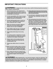
It is especially important for foot protection. 10. Apply the decal in the literature. 2. Keep hands and feet away from the training system when performing an exercise that all users of the training system are adequately informed of 35 or persons with great force. Never release the press arm, butterfly arms, leg lever, lat bar, or nylon strap while weights are exercising, stop immediately and begin cooling down. 14. If you are raised;the weights will fall with pre-existing health problems. Read all instructions before using. Keep children under the age of the owner ...
It is especially important for foot protection. 10. Apply the decal in the literature. 2. Keep hands and feet away from the training system when performing an exercise that all users of the training system are adequately informed of 35 or persons with great force. Never release the press arm, butterfly arms, leg lever, lat bar, or nylon strap while weights are exercising, stop immediately and begin cooling down. 14. If you are raised;the weights will fall with pre-existing health problems. Read all instructions before using. Keep children under the age of the owner ...
English Manual
Page 4
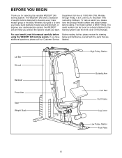
...help us assist you want. until 6 p.m. Whether your goal is WESY19002. If you for selecting the versatile WEIDER® 245 training system. The WEIDER® 245 offers a selection of weight stations designed to develop every major muscle group of this manual carefully before calling. ... specific results you , please note the product model number and serial number before Before reading further, please review the drawing using the WEIDER® 245 training system. Department toll-free at 1-800-999-3756, Monday through Friday, 6 a.m. BEFORE YOU BEGIN Thank you have below and...
...help us assist you want. until 6 p.m. Whether your goal is WESY19002. If you for selecting the versatile WEIDER® 245 training system. The WEIDER® 245 offers a selection of weight stations designed to develop every major muscle group of this manual carefully before calling. ... specific results you , please note the product model number and serial number before Before reading further, please review the drawing using the WEIDER® 245 training system. Department toll-free at 1-800-999-3756, Monday through Friday, 6 a.m. BEFORE YOU BEGIN Thank you have below and...
English Manual
Page 5
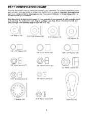
The number in assembly. Note: Assembly is packaged separately. PART IDENTIFICATION CHART This chart is provided to help you identify the small parts used in parenthesis below each part refers to the key number of the part, from the PART LIST on page 22. If you begin each stage is divided into four stages: 1) frame assembly, 2) arm assembly, 3) cable assembly, and 4) seat assembly. Unless otherwise directed, wait until you cannot find a part in the parts bags, check to open that parts bag. 1/4" Washer (78) 5/16" SAE Washer (88) 5/16" Washer (70) 3/8"Washer (9) 1/2" x 1/2" ...
The number in assembly. Note: Assembly is packaged separately. PART IDENTIFICATION CHART This chart is provided to help you identify the small parts used in parenthesis below each part refers to the key number of the part, from the PART LIST on page 22. If you begin each stage is divided into four stages: 1) frame assembly, 2) arm assembly, 3) cable assembly, and 4) seat assembly. Unless otherwise directed, wait until you cannot find a part in the parts bags, check to open that parts bag. 1/4" Washer (78) 5/16" SAE Washer (88) 5/16" Washer (70) 3/8"Washer (9) 1/2" x 1/2" ...
English Manual
Page 7
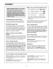
ASSEMBLY Make Assembly Easier for Yourself Everything in this manual is designed to easily identify parts during each assembly step. Make sure you have divided the assembly process into four stages. Refer to it will be used in assembly, we have the following tools: • Two (2) adjustable wrenches • One (1) standard screwdriver • One (1) phillips screwdriver • One (1) rubber mallet • You will assemble the arms and the leg lever. Tightening Parts Tighten all parts as possible, we have a socket set, a set of hours. until assembly is ...
ASSEMBLY Make Assembly Easier for Yourself Everything in this manual is designed to easily identify parts during each assembly step. Make sure you have divided the assembly process into four stages. Refer to it will be used in assembly, we have the following tools: • Two (2) adjustable wrenches • One (1) standard screwdriver • One (1) phillips screwdriver • One (1) rubber mallet • You will assemble the arms and the leg lever. Tightening Parts Tighten all parts as possible, we have a socket set, a set of hours. until assembly is ...
English Manual
Page 8
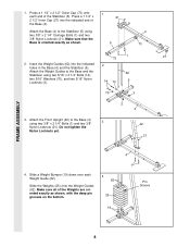
Insert the Weight Guides (62) into the indicated end of the Base (4). Attach the Front Upright (42) to the Base (4) using two 3/8" x 2 1/4" Carriage Bolts (1) and two 3/8" Nylon Locknuts (21). Slide the Weights (25) onto the Weight Guides (62). Make sure all of the Stabilizer (5). Press a 1 1/2" x 2 1/2" Outer Cap (73) onto each Weight Guide (62). Attach the Base (4) to the Base and the 62 Stabilizer using two 5/16" x 3 1/4" Bolts (14), two 5/16" Washers (70), and two 5/16" Nylon Locknuts (3). 14 70 5 70 3 3. Make sure that the Base is oriented exactly as shown, ...
Insert the Weight Guides (62) into the indicated end of the Base (4). Attach the Front Upright (42) to the Base (4) using two 3/8" x 2 1/4" Carriage Bolts (1) and two 3/8" Nylon Locknuts (21). Slide the Weights (25) onto the Weight Guides (62). Make sure all of the Stabilizer (5). Press a 1 1/2" x 2 1/2" Outer Cap (73) onto each Weight Guide (62). Attach the Base (4) to the Base and the 62 Stabilizer using two 5/16" x 3 1/4" Bolts (14), two 5/16" Washers (70), and two 5/16" Nylon Locknuts (3). 14 70 5 70 3 3. Make sure that the Base is oriented exactly as shown, ...
English Manual
Page 9
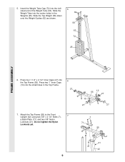
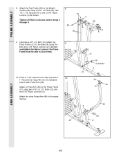
Slide the Top Weight (56) down onto the Weight Guides (62) as shown. 5 62 56 63 72 25 FRAME ASSEMBLY 6. Press four 1 1/2" x 2 1/2" Inner Caps (27) into the indicated end of the Weight Tube (63). Insert the Weight Tube Cap (72) into the Top Frame (55). Press two 1" Inner Caps (10) into the center holes in the Top Frame. 6 27 7. Slide the Weight Tube into the small holes in the Weights (25). Do not tighten the Nylon Locknuts yet. 10 55 27 10 27 27 7 71 55 21 21 42 9 5. Attach the Top Frame (55) to the Front Upright (42) using two 3/8" x 2 1/2" Bolts (7), 7 a ...
Slide the Top Weight (56) down onto the Weight Guides (62) as shown. 5 62 56 63 72 25 FRAME ASSEMBLY 6. Press four 1 1/2" x 2 1/2" Inner Caps (27) into the indicated end of the Weight Tube (63). Insert the Weight Tube Cap (72) into the Top Frame (55). Press two 1" Inner Caps (10) into the center holes in the Top Frame. 6 27 7. Slide the Weight Tube into the small holes in the Weights (25). Do not tighten the Nylon Locknuts yet. 10 55 27 10 27 27 7 71 55 21 21 42 9 5. Attach the Top Frame (55) to the Front Upright (42) using two 3/8" x 2 1/2" Bolts (7), 7 a ...
English Manual
Page 10
Lubricate a 3/8" x 4" Bolt (16). Attach the 9 Press Frame (17) to the Weight Guides (62) using a 5/16" x 6" Bolt (60), two 1/2" x 1/2" Spacers (61), and a 5/16" Nylon Locknut (3) as shown. Press a 1 3/4" Square Inner Cap (44) and a 10 1" Round Inner Cap (49) into the indicated end of each Press Arm (46). Attach the Top Frame (55) to the Base (4) using two 5/16" x 2 1/2" Bolts (22) and two 5/16" Nylon Locknuts (3). Do not overtighten the Nylon Locknut; Attach a Press Arm (46) to pivot freely. 10. FRAME ASSEMBLY 8. Attach the other Press Arm (46) in steps 3 through 8. ...
Lubricate a 3/8" x 4" Bolt (16). Attach the 9 Press Frame (17) to the Weight Guides (62) using a 5/16" x 6" Bolt (60), two 1/2" x 1/2" Spacers (61), and a 5/16" Nylon Locknut (3) as shown. Press a 1 3/4" Square Inner Cap (44) and a 10 1" Round Inner Cap (49) into the indicated end of each Press Arm (46). Attach the Top Frame (55) to the Base (4) using two 5/16" x 2 1/2" Bolts (22) and two 5/16" Nylon Locknuts (3). Do not overtighten the Nylon Locknut; Attach a Press Arm (46) to pivot freely. 10. FRAME ASSEMBLY 8. Attach the other Press Arm (46) in steps 3 through 8. ...
English Manual
Page 11
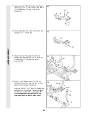
Attach the Seat Plate (37) to the Seat Frame (36) using a 1/4" x 2 1/4" Carriage Bolt (38), a 1/4" Flat Washer (78), and a 1/4" Nylon Locknut (2). 38 36 37 12. Press a 1 1/2" Square Inner Cap (32) into each end of the Leg Lever (29) and the indi- 14 cated end of the Seat Frame (36). Lubricate a 5/16" x 2 1/2" Bolt (22). Attach the Leg Lever (29) to the Seat Frame 11 (36) using the Bolt and a 5/16" Nylon Locknut (3). the Leg Lever must be able to the Front 13 Upright (42) using a #10 x 1" Screw (80). 78 2 36 11 80 ARM ASSEMBLY 13. Attach the Seat Frame (36) to ...
Attach the Seat Plate (37) to the Seat Frame (36) using a 1/4" x 2 1/4" Carriage Bolt (38), a 1/4" Flat Washer (78), and a 1/4" Nylon Locknut (2). 38 36 37 12. Press a 1 1/2" Square Inner Cap (32) into each end of the Leg Lever (29) and the indi- 14 cated end of the Seat Frame (36). Lubricate a 5/16" x 2 1/2" Bolt (22). Attach the Leg Lever (29) to the Seat Frame 11 (36) using the Bolt and a 5/16" Nylon Locknut (3). the Leg Lever must be able to the Front 13 Upright (42) using a #10 x 1" Screw (80). 78 2 36 11 80 ARM ASSEMBLY 13. Attach the Seat Frame (36) to ...
English Manual
Page 12
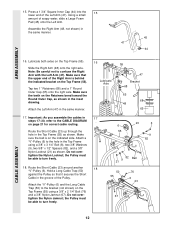
Assemble the Right Arm (48, not shown) in the same manner. 17. Make sure that it secures the Short Cable in the groove of the Right Arm is on the Top Frame (55). Tap two 1" Retainers (68) and a 1" Round Outer Cap (65) onto the right axle. Make sure the teeth on the Top Frame (55). the Pulley must be able to the bracket (not shown) on page 21 for correct cable routing. Route the Short Cable (23) around another "V"-Pulley (6). Do not overtighten the Nylon Jamnut; ARM ASSEMBLY 15. Route the Short Cable (23) up through the hole in the inset drawing. Hold a Long ...
Assemble the Right Arm (48, not shown) in the same manner. 17. Make sure that it secures the Short Cable in the groove of the Right Arm is on the Top Frame (55). Tap two 1" Retainers (68) and a 1" Round Outer Cap (65) onto the right axle. Make sure the teeth on the Top Frame (55). the Pulley must be able to the bracket (not shown) on page 21 for correct cable routing. Route the Short Cable (23) around another "V"-Pulley (6). Do not overtighten the Nylon Jamnut; ARM ASSEMBLY 15. Route the Short Cable (23) up through the hole in the inset drawing. Hold a Long ...
English Manual
Page 13
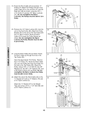
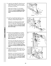
Attach the Pulley Bracket (20) to the rod on the Top Frame (55). Loop the Short Cable (23) as shown. the Pulleys must be able to turn freely. 23 47 21 48 20. Route the Short Cable up through the Pulley Bracket as shown, using two 3/8" x 6 2 1/2" Bolts (7) and two 3/8" Nylon Locknuts (21). Open the bag marked "Pro-Pulley". Attach the end of the Short Cable (23) to pivot freely. 81 23 21. CABLE ASSEMBLY 19. Route the Short Cable (23) over the Pulley and insert the Pulley into the hole in the Top Frame (55). Route the Short Cable (23) around two "V"- 19...
Attach the Pulley Bracket (20) to the rod on the Top Frame (55). Loop the Short Cable (23) as shown. the Pulleys must be able to turn freely. 23 47 21 48 20. Route the Short Cable up through the Pulley Bracket as shown, using two 3/8" x 6 2 1/2" Bolts (7) and two 3/8" Nylon Locknuts (21). Open the bag marked "Pro-Pulley". Attach the end of the Short Cable (23) to pivot freely. 81 23 21. CABLE ASSEMBLY 19. Route the Short Cable (23) over the Pulley and insert the Pulley into the hole in the Top Frame (55). Route the Short Cable (23) around two "V"- 19...
English Manual
Page 14
Lay the Long Cable in the groove. the Pulley must be able to the bracket using a 3/8" x 4 1/4" Bolt (64), a 3/8" Washer (9), and a 3/8" Nylon Locknut (21). Reattach a Pulley Plate to turn freely. 23 17 21 Bracket 24 9 21 42 66 77 12 69 4 64 15 69 25. Hold a Cable Trap (66) against the Pulley so that the Cable is held securely in the bracket on the Base. Attach the Pro-Pulley (77) to turn freely. 24. the Pulley must be able to each side of the Pulley with a 3/8" x 2" Bolt (12) and a 3/8" Nylon Locknut (21). Remove the pre-assembled 3 1/2" Pulleys (15) from the Pulley ...
Lay the Long Cable in the groove. the Pulley must be able to the bracket using a 3/8" x 4 1/4" Bolt (64), a 3/8" Washer (9), and a 3/8" Nylon Locknut (21). Reattach a Pulley Plate to turn freely. 23 17 21 Bracket 24 9 21 42 66 77 12 69 4 64 15 69 25. Hold a Cable Trap (66) against the Pulley so that the Cable is held securely in the bracket on the Base. Attach the Pro-Pulley (77) to turn freely. 24. the Pulley must be able to each side of the Pulley with a 3/8" x 2" Bolt (12) and a 3/8" Nylon Locknut (21). Remove the pre-assembled 3 1/2" Pulleys (15) from the Pulley ...
English Manual
Page 15
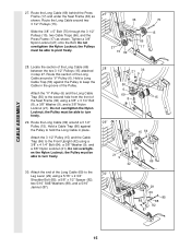
Route the Long Cable around a 3 1/2" Pulley (15). Route this section of the Long Cable (69) between the two 3 1/2" Pulleys (15) attached in step 27. the Pulley must be able to turn freely. 29. Do not overtighten the Nylon Locknut; Slide the 3/8" x 5" Bolt (75) through the 3 1/2" Pulleys (15), two Cable Traps (66), and the Press Frame (17) as shown. Hold a Cable Trap (66) against the Pulley to pivot freely. 27 36 66 21 17 15 69 75 15 28. the Pulley must be able to keep the Cable in place. Do not overtighten the Nylon Locknut; Locate the section of the...
Route the Long Cable around a 3 1/2" Pulley (15). Route this section of the Long Cable (69) between the two 3 1/2" Pulleys (15) attached in step 27. the Pulley must be able to turn freely. 29. Do not overtighten the Nylon Locknut; Slide the 3/8" x 5" Bolt (75) through the 3 1/2" Pulleys (15), two Cable Traps (66), and the Press Frame (17) as shown. Hold a Cable Trap (66) against the Pulley to pivot freely. 27 36 66 21 17 15 69 75 15 28. the Pulley must be able to keep the Cable in place. Do not overtighten the Nylon Locknut; Locate the section of the...
English Manual
Page 16
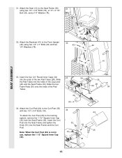
Slide the four Foam Pads (30) onto the ends of the two Pad Tubes (28). Attach the Curl Pad (24) to the Curl Post (35) with two 1/4" x 3/4" Bolts (18). 34 24 To attach the Curl Post (35) to the Front Upright (42) using two 1/4" x 3/4" Bolts (18), a 1/4" x 2 1/4" Bolt (33), and a 1/4" Washer (78). 13 32. Attach the Seat (13) to the Seat Frame (36) 31 using two 1/4" x 3" Bolts (43) and two 1/4" Washers (78). 36 78 33 18 32 43 42 78 43 78 41 SEAT ASSEMBLY 33. Insert the Curl Post into the Seat Frame and tighten the Knob (51) into the holes in 51 use, replace the 1 ...
Slide the four Foam Pads (30) onto the ends of the two Pad Tubes (28). Attach the Curl Pad (24) to the Curl Post (35) with two 1/4" x 3/4" Bolts (18). 34 24 To attach the Curl Post (35) to the Front Upright (42) using two 1/4" x 3/4" Bolts (18), a 1/4" x 2 1/4" Bolt (33), and a 1/4" Washer (78). 13 32. Attach the Seat (13) to the Seat Frame (36) 31 using two 1/4" x 3" Bolts (43) and two 1/4" Washers (78). 36 78 33 18 32 43 42 78 43 78 41 SEAT ASSEMBLY 33. Insert the Curl Post into the Seat Frame and tighten the Knob (51) into the holes in 51 use, replace the 1 ...
English Manual
Page 17
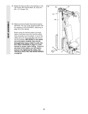
Before using four 55 79 #8 x 1/2" Screws (79). 79 36. See the CABLE DIAGRAM on page 18 of this manual. See TROUBLE-SHOOTING AND MAINTENANCE on the 35 Top Frame (55) and the Base (4) using the training system, pull each cable a few times to remove it by tightening the cables. Make sure that the cables move smoothly, find and correct the problem. If there is used. If one of the remaining parts will be explained in the cables, you will need to be damaged when heavy weight is any slack in ADJUSTMENT, beginning on page 21 of this manual for proper cable routing. ...
Before using four 55 79 #8 x 1/2" Screws (79). 79 36. See the CABLE DIAGRAM on page 18 of this manual. See TROUBLE-SHOOTING AND MAINTENANCE on the 35 Top Frame (55) and the Base (4) using the training system, pull each cable a few times to remove it by tightening the cables. Make sure that the cables move smoothly, find and correct the problem. If there is used. If one of the remaining parts will be explained in the cables, you will need to be damaged when heavy weight is any slack in ADJUSTMENT, beginning on page 21 of this manual for proper cable routing. ...
English Manual
Page 18
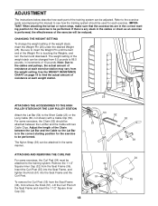
CHANGING THE WEIGHT SETTING To change the weight setting of the Weight Pin is any slack in increments of the Chain between the Lat Bar and the Cable with a Cable Clip (53). Note: Due to the cables and pulleys, the actual amount of resistance at each exercise station may vary from the Seat Frame (36). For some exercises, the Curl Pad (24) must be used for each part of resistance at each weight station. ATTACHING AND REMOVING THE CURL PAD For some exercises, the Chain (52) should be attached to be adjusted. Lift the Curl Post off the Seat Frame and insert the 1 1/2" Square ...
CHANGING THE WEIGHT SETTING To change the weight setting of the Weight Pin is any slack in increments of the Chain between the Lat Bar and the Cable with a Cable Clip (53). Note: Due to the cables and pulleys, the actual amount of resistance at each exercise station may vary from the Seat Frame (36). For some exercises, the Curl Pad (24) must be used for each part of resistance at each weight station. ATTACHING AND REMOVING THE CURL PAD For some exercises, the Chain (52) should be attached to be adjusted. Lift the Curl Post off the Seat Frame and insert the 1 1/2" Square ...
English Manual
Page 19
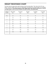
top weight. weight plates. WEIGHT PLATES High Pulley (lbs.) Arm Press (lbs.) Butterfly (lbs.) Leg Raise (lbs.) Low Pulley (lbs.) Top 22 22 20 18 15 1 38 42 39 32 31 2 53 62 58 47 47 3 69 82 77 62 62 4 84 102 98 77 78 5 100 122 114 91 94 6 115 142 133 106 110 7 131 162 152 121 125 8 146 182 171 136 141 19 The other numbers refer to differences in individual weight plates, as well as friction between the cables, pulleys, and weight guides. The butterfly arm resistance listed is the resistance for each butterfly arm.The actual ...
top weight. weight plates. WEIGHT PLATES High Pulley (lbs.) Arm Press (lbs.) Butterfly (lbs.) Leg Raise (lbs.) Low Pulley (lbs.) Top 22 22 20 18 15 1 38 42 39 32 31 2 53 62 58 47 47 3 69 82 77 62 62 4 84 102 98 77 78 5 100 122 114 91 94 6 115 142 133 106 110 7 131 162 152 121 125 8 146 182 171 136 141 19 The other numbers refer to differences in individual weight plates, as well as friction between the cables, pulleys, and weight guides. The butterfly arm resistance listed is the resistance for each butterfly arm.The actual ...
English Manual
Page 20
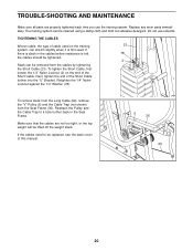
To tighten the Short Cable, first loosen the 1/4" Nylon Locknut (2) on the end of cable used on the training 23 system, can stretch slightly when it is first used. Retighten the 1/4" Nylon Locknut against the 1/4" Washer (78). Make sure that the cables are properly tightened each time you use solvents. Do not use the training system. To remove slack from the Long Cable (69), remove the "V"-Pulley (6) and the Cable Trap (not shown) from the cables by tightening the Short Cable (23). The training system can be replaced, see the back cover of the Short Cable further into the "U" ...
To tighten the Short Cable, first loosen the 1/4" Nylon Locknut (2) on the end of cable used on the training 23 system, can stretch slightly when it is first used. Retighten the 1/4" Nylon Locknut against the 1/4" Washer (78). Make sure that the cables are properly tightened each time you use solvents. Do not use the training system. To remove slack from the Long Cable (69), remove the "V"-Pulley (6) and the Cable Trap (not shown) from the cables by tightening the Short Cable (23). The training system can be replaced, see the back cover of the Short Cable further into the "U" ...
English Manual
Page 21
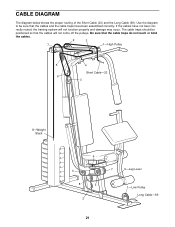
Use the diagram to be positioned so that the cables will not function properly and damage may occur. If the cables have been assembled correctly. Be sure that the cables and the cable traps have not been cor- CABLE DIAGRAM The diagram below shows the proper routing of the Short Cable (23) and the Long Cable (69). The cable traps should be sure that the cable traps do not touch or bind the cables. 2 3 7 1-High Pulley 5 4 Short Cable-23 6 3 8-Weight Stack 6 4 8 5 2 7 9-Leg Lever 1-Low Pulley Long Cable-69 21 rectly routed, the training system will not come...
Use the diagram to be positioned so that the cables will not function properly and damage may occur. If the cables have been assembled correctly. Be sure that the cables and the cable traps have not been cor- CABLE DIAGRAM The diagram below shows the proper routing of the Short Cable (23) and the Long Cable (69). The cable traps should be sure that the cable traps do not touch or bind the cables. 2 3 7 1-High Pulley 5 4 Short Cable-23 6 3 8-Weight Stack 6 4 8 5 2 7 9-Leg Lever 1-Low Pulley Long Cable-69 21 rectly routed, the training system will not come...