
Owners Manual
Page 2
.... Improper assembly may be within 24 inches of the top, bottom, back or sides of natural gas in an LP unit or LP gas in a natural gas unit is in the storage area under or near this barbecue. Do not operate the Weber Gas Barbecue if there is out. Get away from the... to property. If you see, smell or hear the hiss of storage, and/or nonuse, the Weber Gas Barbecue should never be checked by children. After a period of escaping gas from LP tank. 2. Your Weber Gas Barbecue should be checked for gas leaks. Use heat-resistant barbecue mitts or gloves when operating...
.... Improper assembly may be within 24 inches of the top, bottom, back or sides of natural gas in an LP unit or LP gas in a natural gas unit is in the storage area under or near this barbecue. Do not operate the Weber Gas Barbecue if there is out. Get away from the... to property. If you see, smell or hear the hiss of storage, and/or nonuse, the Weber Gas Barbecue should never be checked by children. After a period of escaping gas from LP tank. 2. Your Weber Gas Barbecue should be checked for gas leaks. Use heat-resistant barbecue mitts or gloves when operating...
Owners Manual
Page 6
...If there are local codes that the areas under or near the Weber Gas Barbecue. 6 With your Weber Gas Barbecue you can be kept outdoors in use combustible materials within 24 inches of the top, bottom, back or sides of flammable vapors and liquids, such as gasoline, alcohol, etc.,... and combustible materials. ■ Never store an extra (spare) LP tank under the control...
...If there are local codes that the areas under or near the Weber Gas Barbecue. 6 With your Weber Gas Barbecue you can be kept outdoors in use combustible materials within 24 inches of the top, bottom, back or sides of flammable vapors and liquids, such as gasoline, alcohol, etc.,... and combustible materials. ■ Never store an extra (spare) LP tank under the control...
Owners Manual
Page 10
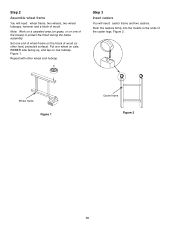
..., two wheel hubcaps, hammer and a block of wood. ER Step 3 Insert casters You will need : caster frame and two casters. Put one wheel on axle, WEBER side facing up, and tap on one end of wheel frame on one of the caster legs. Push the casters firmly into the inserts in the...
..., two wheel hubcaps, hammer and a block of wood. ER Step 3 Insert casters You will need : caster frame and two casters. Put one wheel on axle, WEBER side facing up, and tap on one end of wheel frame on one of the caster legs. Push the casters firmly into the inserts in the...

Owners Manual
Page 11
...to the bolt. Tighten. Figure 4. Fuel scale decal Figure 4 slots to the outside. Figure 3. The fuel scale decal should be on back side Figure 3 slots to the outside Wheel frame 11 Note: Fuel scale decal on wheel frame must be toward the front. Tighten bolt with the ... up to the wheel frame, slots to the outside . Add the nylon washer to the bolt. Hold the other bottom connector. (a) Turn frame assembly right side up. Step 4 Continue frame assembly You will need: Wheel frame, caster frame, two bottom connectors, four 1/4-20 x 3 1/2 inch bolts, four nylon washers ...
...to the bolt. Tighten. Figure 4. Fuel scale decal Figure 4 slots to the outside. Figure 3. The fuel scale decal should be on back side Figure 3 slots to the outside Wheel frame 11 Note: Fuel scale decal on wheel frame must be toward the front. Tighten bolt with the ... up to the wheel frame, slots to the outside . Add the nylon washer to the bolt. Hold the other bottom connector. (a) Turn frame assembly right side up. Step 4 Continue frame assembly You will need: Wheel frame, caster frame, two bottom connectors, four 1/4-20 x 3 1/2 inch bolts, four nylon washers ...

Owners Manual
Page 12
... the match holder bracket and frame.Figure 5. Align the match holder with a wrench. (If you try to your left. Insert the bolt. View from underneath side of frame Step 6 Assemble front top frame rail You will need : one top frame rail #1, one top frame rail #2, one plastic button, match holder bracket...
... the match holder bracket and frame.Figure 5. Align the match holder with a wrench. (If you try to your left. Insert the bolt. View from underneath side of frame Step 6 Assemble front top frame rail You will need : one top frame rail #1, one top frame rail #2, one plastic button, match holder bracket...

Owners Manual
Page 13
... wrong way. Figure 8 (a). Figure 8 (b). Turn top frame rail #2 around.) Note: Do not use a washer for this step. (a) (b) Front caster frame Fuel scale decal on front side Figure 7 Front wheel frame 1 2 Figure 8 13 Put top frame rail #1 to your left and top frame rail #2 to your right. Figure 7 (a).
... wrong way. Figure 8 (a). Figure 8 (b). Turn top frame rail #2 around.) Note: Do not use a washer for this step. (a) (b) Front caster frame Fuel scale decal on front side Figure 7 Front wheel frame 1 2 Figure 8 13 Put top frame rail #1 to your left and top frame rail #2 to your right. Figure 7 (a).

Owners Manual
Page 16
..., 1/4-20 x 1 3/4 inch bolt, 1/4-20 hex nut, two 1/4 inch nylon washers, pliers, and a 7/16 inch or adjustable wrench. Tabs on the left View from front left side of wheel frame Figure 13 16 Make sure indicator rod of fuel scale is on tank panel Wheel frame (b) E E F F View from front right Figure 14...
..., 1/4-20 x 1 3/4 inch bolt, 1/4-20 hex nut, two 1/4 inch nylon washers, pliers, and a 7/16 inch or adjustable wrench. Tabs on the left View from front left side of wheel frame Figure 13 16 Make sure indicator rod of fuel scale is on tank panel Wheel frame (b) E E F F View from front right Figure 14...

Owners Manual
Page 21
Hook the LP tank onto the fuel scale. Push the male fitting of the regulator into the threaded hole in the side of the wheel frame leg. Close by turning clockwise. Swing ... disconnect, and maintain pressure. The hose and regulator are connected in side of the wheel frame leg. ƽWARNING: Make sure that the LP tank valve is closed . Loosen the tank lock wing nut. Figure...Hose Hole in the following manner: Slide back the collar of the tank and regulator. Step 18 Connect LP tank You will need: hose clamp and 1/4-20 x5/8 screw, regular screwdriver. ƽWARNING: Make sure...
Hook the LP tank onto the fuel scale. Push the male fitting of the regulator into the threaded hole in the side of the wheel frame leg. Close by turning clockwise. Swing ... disconnect, and maintain pressure. The hose and regulator are connected in side of the wheel frame leg. ƽWARNING: Make sure that the LP tank valve is closed . Loosen the tank lock wing nut. Figure...Hose Hole in the following manner: Slide back the collar of the tank and regulator. Step 18 Connect LP tank You will need: hose clamp and 1/4-20 x5/8 screw, regular screwdriver. ƽWARNING: Make sure...

Owners Manual
Page 26
... the rear of the cooking box and the top frame rails. Set the right work surface over the top of the handles on the left side. Figure 37 (b). Step 24 Install left work surface and glides You will need : right work surface, two nylon (plastic) glides, two Phillips head 1/4-20... x 1 inch machine screws and a Phillips screwdriver. Thread screw in the left work surface will cover half of the handles on the right side. Position the glide as shown in and tighten with a Phillips screwdriver. Set the left work surface and the glide. Figure 36 (b). Figure 36. ...
... the rear of the cooking box and the top frame rails. Set the right work surface over the top of the handles on the left side. Figure 37 (b). Step 24 Install left work surface and glides You will need : right work surface, two nylon (plastic) glides, two Phillips head 1/4-20... x 1 inch machine screws and a Phillips screwdriver. Thread screw in the left work surface will cover half of the handles on the right side. Position the glide as shown in and tighten with a Phillips screwdriver. Set the left work surface and the glide. Figure 36 (b). Figure 36. ...
Owners Manual
Page 27
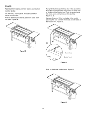
With the Weber logo to lift the front edge of the control panel slightly and set it into place. ...buttons up until they stay in the up position. Figure 38 (a) Front Panel Control Panel Figure 39 Push on both sides of the cooking box. Place the control panel into place, using even pressure while pushing. Push the control panel into ...the grooves on either side of the front of the cooking box. Figure 39 (a). Figure 39. Figure 40 27 Step 26 Reinstall front panel,...
With the Weber logo to lift the front edge of the control panel slightly and set it into place. ...buttons up until they stay in the up position. Figure 38 (a) Front Panel Control Panel Figure 39 Push on both sides of the cooking box. Place the control panel into place, using even pressure while pushing. Push the control panel into ...the grooves on either side of the front of the cooking box. Figure 39 (a). Figure 39. Figure 40 27 Step 26 Reinstall front panel,...