

User Manual
Page 1
... 36. Parts Check List 5. Connection of Range Indication 29. Handset and Base Unit Security Codes 11. Home Area Code 14. Line in Handset 8. Live Dialing 17. Mute 19. Announced Transfer 26. Charging of Inbound Call 23. Ringer Volume Control 10. Handset Name 13. Caller ID 22. Conference 27. Tone/Pulse 13. Auto Pick Up 15. Speed Dial Memory 20. Caller ID Display of Handset Battery Pack 9. Visual Message Waiting Indication 26. Wall Mounting 17.Basic Operations 17. To Delete ALL Speed Memory Locations 21. Dialing from Speed Memory 22.Advanced...
... 36. Parts Check List 5. Connection of Range Indication 29. Handset and Base Unit Security Codes 11. Home Area Code 14. Line in Handset 8. Live Dialing 17. Mute 19. Announced Transfer 26. Charging of Inbound Call 23. Ringer Volume Control 10. Handset Name 13. Caller ID 22. Conference 27. Tone/Pulse 13. Auto Pick Up 15. Speed Dial Memory 20. Caller ID Display of Handset Battery Pack 9. Visual Message Waiting Indication 26. Wall Mounting 17.Basic Operations 17. To Delete ALL Speed Memory Locations 21. Dialing from Speed Memory 22.Advanced...

User Manual
Page 2
...-2421 / 40-2420 is an advanced 4-line cordless telephone system that could be placed in a built-in a risk of power source indicated on an active call : In the United States: VTECH COMMUNICATIONS 1-800-595-9511 In Canada: VTECH ELECTRONICS 1-800-267-7311 2 3 We strongly recommend you are provided for ventilation. To order additional system Handsets (model# VT 40-2420), battery packs, or headsets, please call...
...-2421 / 40-2420 is an advanced 4-line cordless telephone system that could be placed in a built-in a risk of power source indicated on an active call : In the United States: VTECH COMMUNICATIONS 1-800-595-9511 In Canada: VTECH ELECTRONICS 1-800-267-7311 2 3 We strongly recommend you are provided for ventilation. To order additional system Handsets (model# VT 40-2420), battery packs, or headsets, please call...

User Manual
Page 3
Parts Check List 1. Handset Charger and power adapter 4. Telephone line cord (x2) 7. Dialing Keys (0-9) 9. PROG 11. LCD Display 12. OFF 14. Headset Jack (2.5mm) 15. SPEAKERPHONE 16. MUTE 17. HS CHARGING LED 4 5 Earpiece 3. HOLD 8. CID 13. Base Unit and power adapter 2. Handset 3. Belt clip The Handset and Handset Charger Layout 1. FLASH 5. REDIAL 7. Wall Mount Bracket 6. INTERCOM 19. Antenna 2. FUNCTION 10. SPARE BATT LED 22. Spare Battery Charging Slot 21. Handset battery pack 5. Volume/Scroll Keys 4. CALLER 18. Microphone 20. Line ...
Parts Check List 1. Handset Charger and power adapter 4. Telephone line cord (x2) 7. Dialing Keys (0-9) 9. PROG 11. LCD Display 12. OFF 14. Headset Jack (2.5mm) 15. SPEAKERPHONE 16. MUTE 17. HS CHARGING LED 4 5 Earpiece 3. HOLD 8. CID 13. Base Unit and power adapter 2. Handset 3. Belt clip The Handset and Handset Charger Layout 1. FLASH 5. REDIAL 7. Wall Mount Bracket 6. INTERCOM 19. Antenna 2. FUNCTION 10. SPARE BATT LED 22. Spare Battery Charging Slot 21. Handset battery pack 5. Volume/Scroll Keys 4. CALLER 18. Microphone 20. Line ...

User Manual
Page 4
... the handset charger. 5. Antenna 4. AUX Dataport Jack 7. Wall Mount Cover 6 •VT 40-2420 setup 1. Plug the AC power adapter into an electrical outlet, and the DC connector 4 into the back of Phone and Power Lines 3 •VT 40-2421 setup 1. There are three modular telephone connections on the back of a fax or modem. Install handset battery and allow direct connection of the base unit. DC Connector 3. Getting Started The Base Unit Layout FRONT 1 2 Setup Connection...
... the handset charger. 5. Antenna 4. AUX Dataport Jack 7. Wall Mount Cover 6 •VT 40-2420 setup 1. Plug the AC power adapter into an electrical outlet, and the DC connector 4 into the back of Phone and Power Lines 3 •VT 40-2421 setup 1. There are three modular telephone connections on the back of a fax or modem. Install handset battery and allow direct connection of the base unit. DC Connector 3. Getting Started The Base Unit Layout FRONT 1 2 Setup Connection...

User Manual
Page 5
... access the program mode, start with the charge contacts in the handset charger, and allow it upwards. 4. If you register additional Handsets to idle mode. Replace the battery cover by pressing on the indent and sliding downward. 2. At any time, you press the keys. If the new battery pack is completely clear and does not activate when you can press the OFF key to make selections. Use the ( / ) volume keys to...
... access the program mode, start with the charge contacts in the handset charger, and allow it upwards. 4. If you register additional Handsets to idle mode. Replace the battery cover by pressing on the indent and sliding downward. 2. At any time, you press the keys. If the new battery pack is completely clear and does not activate when you can press the OFF key to make selections. Use the ( / ) volume keys to...

User Manual
Page 6
... to PLS ENTER CODE, waiting for LINE 2, LINE 3 and LINE 4 Ringer Type • Access program mode • Press the ( ) key until you see RINGER TYPE • Press the # key to change settings. The HS SECURITY CODE has now been loaded into the Base Unit, ERROR! Handset ID The VT 40-2421 system supports up to confirm choice • PROGRAMMING SUCCESSFUL! The cursor will blink to the right of the current ringer setting • Use the ( / ) volume keys to sample...
... to PLS ENTER CODE, waiting for LINE 2, LINE 3 and LINE 4 Ringer Type • Access program mode • Press the ( ) key until you see RINGER TYPE • Press the # key to change settings. The HS SECURITY CODE has now been loaded into the Base Unit, ERROR! Handset ID The VT 40-2421 system supports up to confirm choice • PROGRAMMING SUCCESSFUL! The cursor will blink to the right of the current ringer setting • Use the ( / ) volume keys to sample...

User Manual
Page 7
... will blink to the right of the current ringer setting. • Use the ( / ) volume keys to choose TONE or PULSE • Press the # key to change the Flash Time. 13 Handset Name If you want to confirm choice • PROGRAMMING SUCCESSFUL! The cursor will be prompted to PLS ENTER NAME • Use the digit keys to 'spell' the name. is displayed. is displayed. is commonly used with service such as Call Waiting. Note...
... will blink to the right of the current ringer setting. • Use the ( / ) volume keys to choose TONE or PULSE • Press the # key to change the Flash Time. 13 Handset Name If you want to confirm choice • PROGRAMMING SUCCESSFUL! The cursor will be prompted to PLS ENTER NAME • Use the digit keys to 'spell' the name. is displayed. is displayed. is commonly used with service such as Call Waiting. Note...

User Manual
Page 8
... Handset ID (extension) number for LOCAL AREA CODE2, CODE3, CODE4 and CODE5 Line in Use Detection There is a LINE IN USE indication when another telephone on the same line (parallel extension) is lifted from the cradle (without having to press LINE or SPEAKERPHONE). • Access program mode • Press the ( ) key until you see LOCAL AREA CODE1 • Press the # key to change settings. Base Reset Select this option to reset a single handset to factory default settings...
... Handset ID (extension) number for LOCAL AREA CODE2, CODE3, CODE4 and CODE5 Line in Use Detection There is a LINE IN USE indication when another telephone on the same line (parallel extension) is lifted from the cradle (without having to press LINE or SPEAKERPHONE). • Access program mode • Press the ( ) key until you see LOCAL AREA CODE1 • Press the # key to change settings. Base Reset Select this option to reset a single handset to factory default settings...

User Manual
Page 9
... wall mount bracket firmly in charger cradle Pre-Dialing • Enter the number you wish to dial on the display. • Press the desired LINE key or SPK.PHONE (for use on standard Wall Mount plates only. • Remove the wall mount cover at the back of the Base Unit • Line up the tabs on next available line). • To end a call press OFF or place handset in place. • Mount the Base Unit...
... wall mount bracket firmly in charger cradle Pre-Dialing • Enter the number you wish to dial on the display. • Press the desired LINE key or SPK.PHONE (for use on standard Wall Mount plates only. • Remove the wall mount cover at the back of the Base Unit • Line up the tabs on next available line). • To end a call press OFF or place handset in place. • Mount the Base Unit...

User Manual
Page 10
..., a ringing handset will receive a Recall Ring tone that serves as a reminder that a call remains on hold. Intercom To establish an intercom call • Press the INTERCOM key, followed by the handset number (01..12). • Once the other handset answers, the handset will automatically disconnect the line. MUTE! Note: If a call is placed on hold for handsfree on ringing line). NOTE: If you have AUTO PICKUP set to answer the ringing line * Press SPK.PHONE...
..., a ringing handset will receive a Recall Ring tone that serves as a reminder that a call remains on hold. Intercom To establish an intercom call • Press the INTERCOM key, followed by the handset number (01..12). • Once the other handset answers, the handset will automatically disconnect the line. MUTE! Note: If a call is placed on hold for handsfree on ringing line). NOTE: If you have AUTO PICKUP set to answer the ringing line * Press SPK.PHONE...
User Manual
Page 11
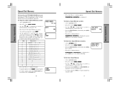
Basic Operations Basic Operations Speed Dial Memory Each handset in the VT 40-2421 / 40-2420 system can be up to 20 names and numbers in a private speed dial memory. is displayed To Delete a Speed Memory Location • Access program mode • Press # to select SPEED MEMORY • Use the ( / ) volume keys to scroll to a desired memory location (01...20) • Press the FUNCTION key followed by the 1 (DEL) key to delete • Press # to confirm deletion • PROGRAMMING SUCCESSFUL! Names...
Basic Operations Basic Operations Speed Dial Memory Each handset in the VT 40-2421 / 40-2420 system can be up to 20 names and numbers in a private speed dial memory. is displayed To Delete a Speed Memory Location • Access program mode • Press # to select SPEED MEMORY • Use the ( / ) volume keys to scroll to a desired memory location (01...20) • Press the FUNCTION key followed by the 1 (DEL) key to delete • Press # to confirm deletion • PROGRAMMING SUCCESSFUL! Names...

User Manual
Page 12
... automatically dial the displayed number. • You can also press the SPK.PHONE key to answer the incoming call received. To answer a particular line, simply press the corresponding LINE key. If more than one line is ringing at the same time, you may not be stored into Speed Dial Memory • Press the CID key • Use the ( / ) volume keys to locate the Caller ID record to the beginning by the VT 40-2421 system...
... automatically dial the displayed number. • You can also press the SPK.PHONE key to answer the incoming call received. To answer a particular line, simply press the corresponding LINE key. If more than one line is ringing at the same time, you may not be stored into Speed Dial Memory • Press the CID key • Use the ( / ) volume keys to locate the Caller ID record to the beginning by the VT 40-2421 system...

User Manual
Page 13
... record • Press the CID key. DEL MSG DISPLAY? Advanced Operations Advanced Operations Caller ID • Press the PROG key • Press # to enter SPEED MEMORY. • Use the ( / ) volume keys to locate the memory location (01..20) where you check your messages, the Message Waiting indicator will automatically turn off. Please note that whenever new, unplayed messages are stored in your voicemail, a Visual Message Waiting Indicator(VMWI) signal is displayed. * Press 1 to delete the MESSAGE WAITING indicator for LINE 1 * Press 2 to delete...
... record • Press the CID key. DEL MSG DISPLAY? Advanced Operations Advanced Operations Caller ID • Press the PROG key • Press # to enter SPEED MEMORY. • Use the ( / ) volume keys to locate the memory location (01..20) where you check your messages, the Message Waiting indicator will automatically turn off. Please note that whenever new, unplayed messages are stored in your voicemail, a Visual Message Waiting Indicator(VMWI) signal is displayed. * Press 1 to delete the MESSAGE WAITING indicator for LINE 1 * Press 2 to delete...

User Manual
Page 14
... one line, and to end the call on the other handset answers, press the FUNCTION key followed by the *(CONF) key to establish the conference call between both handsets and the outside line. • Either handset can also press OFF to end the intercom at any time. Advanced Operations Advanced Operations Transfer Announced Transfer • While on an active call, press the INTERCOM key followed by the handset number you...
... one line, and to end the call on the other handset answers, press the FUNCTION key followed by the *(CONF) key to establish the conference call between both handsets and the outside line. • Either handset can also press OFF to end the intercom at any time. Advanced Operations Advanced Operations Transfer Announced Transfer • While on an active call, press the INTERCOM key followed by the handset number you...

User Manual
Page 15
... uninterrupted service. Connect the plug on the cordless Handset. The plug should replace the drained battery pack immediately. NOTE : Whenever a compatible Headset is compatible with the charge contacts facing down. If you should fit securely. The spare battery pack can be used to the cordless Handset, the microphone on a call when the OUT OF RANGE alert appears, you will hear a double beep every 10 seconds, indicating that a spare battery should be muted...
... uninterrupted service. Connect the plug on the cordless Handset. The plug should replace the drained battery pack immediately. NOTE : Whenever a compatible Headset is compatible with the charge contacts facing down. If you should fit securely. The spare battery pack can be used to the cordless Handset, the microphone on a call when the OUT OF RANGE alert appears, you will hear a double beep every 10 seconds, indicating that a spare battery should be muted...

User Manual
Page 16
... cords. The Phone Doesn't Work At All • Make sure the Handset Security Code is properly loaded into the Base Unit. • Make sure the Power Cord is plugged into the same circuit as the Base Unit can sometimes cause power surges harmful to another position. • Make sure the Base Unit Antenna is plugged firmly into water, DO NOT RETRIEVE IT UNTIL YOU UNPLUG THE POWER CORD AND TELEPHONE LINE CORDS FROM THE WALL...
... cords. The Phone Doesn't Work At All • Make sure the Handset Security Code is properly loaded into the Base Unit. • Make sure the Power Cord is plugged into the same circuit as the Base Unit can sometimes cause power surges harmful to another position. • Make sure the Base Unit Antenna is plugged firmly into water, DO NOT RETRIEVE IT UNTIL YOU UNPLUG THE POWER CORD AND TELEPHONE LINE CORDS FROM THE WALL...

User Manual
Page 17
... the Base Unit and the telephone jack(s). You Hear Other Calls While Using Your Phone • Disconnect your Base Unit from the Base Unit. • You may be responding normally, then try putting the Handset in the cradle. Disconnect the power to the Base. 5. Re-install the battery pack (s) 6. ONE YEAR. Additional Information Additional Information 32 33 To set the ringer, see RINGER CONTROL. • Make sure the telephone line cord(s) is...
... the Base Unit and the telephone jack(s). You Hear Other Calls While Using Your Phone • Disconnect your Base Unit from the Base Unit. • You may be responding normally, then try putting the Handset in the cradle. Disconnect the power to the Base. 5. Re-install the battery pack (s) 6. ONE YEAR. Additional Information Additional Information 32 33 To set the ringer, see RINGER CONTROL. • Make sure the telephone line cord(s) is...

User Manual
Page 18
... POWER REQUIREMENTS Handset : Base : Charger: 3.6 VDC NiMH Battery Pack 9 V 1000mA 9 V 500mA MEMORY Speed Dial: 20 Memory locations - You may also have been modified or incorporated into other rights which may have other products • Products purchased and/or operated outside the USA, its territories, or Canada. • Products serviced by the owner or a service facility not expressly authorized by FCC and IC. Actual operating range...
... POWER REQUIREMENTS Handset : Base : Charger: 3.6 VDC NiMH Battery Pack 9 V 1000mA 9 V 500mA MEMORY Speed Dial: 20 Memory locations - You may also have been modified or incorporated into other rights which may have other products • Products purchased and/or operated outside the USA, its territories, or Canada. • Products serviced by the owner or a service facility not expressly authorized by FCC and IC. Actual operating range...

User Manual
Page 19
... ring when you may make changes in a residential installation. If so, you to radio or television reception, which is registered for the United States. It also complies with Parts 15 of the following two conditions: (1) this equipment from the line network until the problem has been corrected. FCC Part 15 Warning: Changes or modifications to the telephone loop which can radiate radio frequency...
... ring when you may make changes in a residential installation. If so, you to radio or television reception, which is registered for the United States. It also complies with Parts 15 of the following two conditions: (1) this equipment from the line network until the problem has been corrected. FCC Part 15 Warning: Changes or modifications to the telephone loop which can radiate radio frequency...

User Manual
Page 20
VTECH TELECOMMUNICATIONS LTD. Dept. V6X 1Z9. Copyright 2001 for VTECH TELECOMMUNICATIONS LTD. A member of THE VTECH GROUP OF COMPANIES. by VTech Electronics Canada Ltd., Suite 200-7671 Alderbridge Way Richmond, B.C. Printed in Canada by VTech Communications Inc, 1145 Coliseum Rd. Vtech San Antonio, TX. 78219 Distributed in China ISSUE 0 Distributed in the U.S.A.
VTECH TELECOMMUNICATIONS LTD. Dept. V6X 1Z9. Copyright 2001 for VTECH TELECOMMUNICATIONS LTD. A member of THE VTECH GROUP OF COMPANIES. by VTech Electronics Canada Ltd., Suite 200-7671 Alderbridge Way Richmond, B.C. Printed in Canada by VTech Communications Inc, 1145 Coliseum Rd. Vtech San Antonio, TX. 78219 Distributed in China ISSUE 0 Distributed in the U.S.A.


