
Quick Installation Guide
Page 1
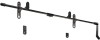
QUICK INSTALL GUIDE QUICK INSTALL SLIM HDTV MOUNT UNIVERSAL FOR 32" - 55" TVS UP TO 100 LBS XMF1000 -
QUICK INSTALL GUIDE QUICK INSTALL SLIM HDTV MOUNT UNIVERSAL FOR 32" - 55" TVS UP TO 100 LBS XMF1000 -
Quick Installation Guide
Page 2
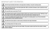
...mounting system supports a maximum weight of 100 lbs and a maximum screen size of this Quick Install Guide. Attaching a screen that could be a choking hazard if swallowed. This mounting system is larger or heavier than specified above may result in personal injury or damage to your TV, do not install the mounting...Important Safety Information on this page before installing or using this Quick Install Guide. Contact a qualified contractor. Only attach this mount system to vertical walls as instructed in this box away from 32" to support the mounting system or your TV. Keep all ...
...mounting system supports a maximum weight of 100 lbs and a maximum screen size of this Quick Install Guide. Attaching a screen that could be a choking hazard if swallowed. This mounting system is larger or heavier than specified above may result in personal injury or damage to your TV, do not install the mounting...Important Safety Information on this page before installing or using this Quick Install Guide. Contact a qualified contractor. Only attach this mount system to vertical walls as instructed in this box away from 32" to support the mounting system or your TV. Keep all ...
Quick Installation Guide
Page 3
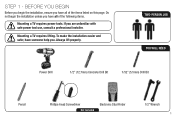
... Electronic Stud Finder 1/2" Wrench 1 Mounting a TV requires lifting. Always lift properly. STEP 1 - BEFORE YOU BEGIN Before you begin the installation unless you have all of the following items. Mounting a TV requires power tools. To make the installation easier and safer, have someone help you are unfamiliar with safe power tool use, consult a professional installer. If you .
... Electronic Stud Finder 1/2" Wrench 1 Mounting a TV requires lifting. Always lift properly. STEP 1 - BEFORE YOU BEGIN Before you begin the installation unless you have all of the following items. Mounting a TV requires power tools. To make the installation easier and safer, have someone help you are unfamiliar with safe power tool use, consult a professional installer. If you .

Quick Installation Guide
Page 6
The wall 1 covering (drywall, lath, plaster, etc.) may not be approximately 16" apart. Drill the hole about 2" into the stud. Use the electronic stud finder to Step 3B on page 10. 1 16" 1. Using the power drill and the 7/32" drill bit, drill into the X mark you are drilling into the...be thicker than 1/2". Use the pencil to walls with an X at the height you are located. STEP 3A - Ensure you just made. MOUNTING TO A WALL WITH WOOD STUDS The mount can be attached to mark the areas of the wall where the studs are mounting on a concrete wall, go to locate two...
The wall 1 covering (drywall, lath, plaster, etc.) may not be approximately 16" apart. Drill the hole about 2" into the stud. Use the electronic stud finder to Step 3B on page 10. 1 16" 1. Using the power drill and the 7/32" drill bit, drill into the X mark you are drilling into the...be thicker than 1/2". Use the pencil to walls with an X at the height you are located. STEP 3A - Ensure you just made. MOUNTING TO A WALL WITH WOOD STUDS The mount can be attached to mark the areas of the wall where the studs are mounting on a concrete wall, go to locate two...

Quick Installation Guide
Page 7
Snap on the leveler (part E) and level the bar. Place part A against the wall. Use Bottom Hole 4. Push the other bracket (part A) onto the bar and hold it is over the stud. Push the bar through the opening in the bracket as shown. Ensure it flat against the wall as shown, and use a wrench to insert the lag bolt and washer into the hole you just drilled. 3. Mark the location of the hole in the bracket (part A) as shown. 4 Push Bar Through Level Bar Make Mark 5 Remove 1 lag bolt and 1 washer from the pouch labeled 3 LAG.
Snap on the leveler (part E) and level the bar. Place part A against the wall. Use Bottom Hole 4. Push the other bracket (part A) onto the bar and hold it is over the stud. Push the bar through the opening in the bracket as shown. Ensure it flat against the wall as shown, and use a wrench to insert the lag bolt and washer into the hole you just drilled. 3. Mark the location of the hole in the bracket (part A) as shown. 4 Push Bar Through Level Bar Make Mark 5 Remove 1 lag bolt and 1 washer from the pouch labeled 3 LAG.

Quick Installation Guide
Page 8
Ensure you just drilled. Do not insert the lag bolts completely. Leave 1/2" of the bolt showing. 5. Remove 1 lag bolt and 1 washer from the wall. Using the power drill and the 7/32" drill bit, drill into the stud. Remove the bar, the leveler, and the unattached bracket (part A) from the pouch labeled LAG. 6 Place the other bracket (part A) against the wall as shown. Drill the hole about 2" into the hole you are drilling into the pencil mark as shown, and use a wrench to insert the lag bolt and washer into the stud. 7/32" 5 Pencil Mark 6. Use Bottom Hole 6
Ensure you just drilled. Do not insert the lag bolts completely. Leave 1/2" of the bolt showing. 5. Remove 1 lag bolt and 1 washer from the wall. Using the power drill and the 7/32" drill bit, drill into the stud. Remove the bar, the leveler, and the unattached bracket (part A) from the pouch labeled LAG. 6 Place the other bracket (part A) against the wall as shown. Drill the hole about 2" into the hole you are drilling into the pencil mark as shown, and use a wrench to insert the lag bolt and washer into the stud. 7/32" 5 Pencil Mark 6. Use Bottom Hole 6

Quick Installation Guide
Page 9
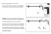
7. Using the power drill and the 7/32" drill bit, drill into the top 2 holes as shown. Make any small adjustments, then use a wrench to which you are drilling into the stud. 7 Level Bar Tighten Bolts 8 7/32" 7 Push the bar through the openings in each bracket (part A) as shown. The bar can be inserted from right to left or left to right, depending on the leveler (part E) and verify that the bar is level. Drill the hole about 2" into the stud. Ensure you would like the handle attached. 8. Snap on the end of the bar to tighten the 2 lag bolts completely.
7. Using the power drill and the 7/32" drill bit, drill into the top 2 holes as shown. Make any small adjustments, then use a wrench to which you are drilling into the stud. 7 Level Bar Tighten Bolts 8 7/32" 7 Push the bar through the openings in each bracket (part A) as shown. The bar can be inserted from right to left or left to right, depending on the leveler (part E) and verify that the bar is level. Drill the hole about 2" into the stud. Ensure you would like the handle attached. 8. Snap on the end of the bar to tighten the 2 lag bolts completely.

Quick Installation Guide
Page 10
Use a wrench to the end of the bar. Attach the handle (part F) to insert the lag bolts and washers as shown. Tighten the bolts completely. 10. 9. Remove 2 lag bolts and 2 washers from the pouch labeled LAG. Tighten the screw completely. 8 9 10 Insert Screw in Bottom Hole Secure the handle to the bar by inserting a screw (part H) into the bottom hole on the handle.
Use a wrench to the end of the bar. Attach the handle (part F) to insert the lag bolts and washers as shown. Tighten the bolts completely. 10. 9. Remove 2 lag bolts and 2 washers from the pouch labeled LAG. Tighten the screw completely. 8 9 10 Insert Screw in Bottom Hole Secure the handle to the bar by inserting a screw (part H) into the bottom hole on the handle.
Quick Installation Guide
Page 11
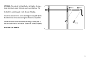
Secure the handle to the extender by inserting a screw (part H) into the bottom hole on page 15. Tighten the screw completely. To attach the extender, push it onto the end of the bar. Tighten the screw completely. H I ) into the bottom hole on the extender. Go to the bar by inserting a screw (part I 9 Secure the extender to Step 4 on the handle. OPTIONAL: The extender can be easier to lengthen the bar. A longer bar may be attached to access when mounting large TVs.
Secure the handle to the extender by inserting a screw (part H) into the bottom hole on page 15. Tighten the screw completely. To attach the extender, push it onto the end of the bar. Tighten the screw completely. H I ) into the bottom hole on the extender. Go to the bar by inserting a screw (part I 9 Secure the extender to Step 4 on the handle. OPTIONAL: The extender can be easier to lengthen the bar. A longer bar may be attached to access when mounting large TVs.

Quick Installation Guide
Page 12
MOUNTING TO A CONCRETE WALL 1. Determine the height at which you just drilled. Using the power drill and the 1/2" concrete drill bit, drill a hole 1/2" into the hole you want the mount to hang. Mark the position of the left bracket hole with the wall. 10 Remove 1 anchor from the pouch labeled ANCHOR. 2 Push the anchor into the pencil mark. Drill about 2 1/2" deep. 1 Pencil Mark 2. Ensure the anchor is completely inserted and flush with a pencil. STEP 3B -
MOUNTING TO A CONCRETE WALL 1. Determine the height at which you just drilled. Using the power drill and the 1/2" concrete drill bit, drill a hole 1/2" into the hole you want the mount to hang. Mark the position of the left bracket hole with the wall. 10 Remove 1 anchor from the pouch labeled ANCHOR. 2 Push the anchor into the pencil mark. Drill about 2 1/2" deep. 1 Pencil Mark 2. Ensure the anchor is completely inserted and flush with a pencil. STEP 3B -

Quick Installation Guide
Page 13
Use Bottom Hole 4. Mark the location of the 3 holes on the leveler (part E) and level the bar. Push the other bracket. Push the bar through the opening in the bracket (part A) as shown. 4 1 16" 2 Level Bar Make Mark 3 11 3. Ensure it flat against the wall as shown, and use a wrench to insert the lag bolt and washer into the anchor. Snap on the brackets as shown. Remove 1 lag bolt and 1 washer from the other bracket (part A) onto the bar and hold it is at least 16" from the pouch labeled 3 LAG. Place a bracket (part A) against the wall.
Use Bottom Hole 4. Mark the location of the 3 holes on the leveler (part E) and level the bar. Push the other bracket. Push the bar through the opening in the bracket (part A) as shown. 4 1 16" 2 Level Bar Make Mark 3 11 3. Ensure it flat against the wall as shown, and use a wrench to insert the lag bolt and washer into the anchor. Snap on the brackets as shown. Remove 1 lag bolt and 1 washer from the other bracket (part A) onto the bar and hold it is at least 16" from the pouch labeled 3 LAG. Place a bracket (part A) against the wall.

Quick Installation Guide
Page 15
... bolts and 3 washers from right to left or left to tighten the 4 lag bolts completely. Push the bar through the openings in each bracket (part A) as shown, and use a wrench to right, depending on the leveler (part E) and verify that the bar is level. Snap on the end of the bolts showing. 8. Place the other bracket (part A) against the wall...
... bolts and 3 washers from right to left or left to tighten the 4 lag bolts completely. Push the bar through the openings in each bracket (part A) as shown, and use a wrench to right, depending on the leveler (part E) and verify that the bar is level. Snap on the end of the bolts showing. 8. Place the other bracket (part A) against the wall...
Quick Installation Guide
Page 16
...hole on the handle. Tighten the screw completely. 9. Go to lengthen the bar. Secure the handle to the bar by inserting a screw (part H) into the bottom hole on the extender. Tighten the screw completely. Attach the handle (part F) to access when mounting large TVs. Secure the extender to... the extender by inserting a screw (part H) into the bottom hole on the handle....
...hole on the handle. Tighten the screw completely. 9. Go to lengthen the bar. Secure the handle to the bar by inserting a screw (part H) into the bottom hole on the extender. Tighten the screw completely. Attach the handle (part F) to access when mounting large TVs. Secure the extender to... the extender by inserting a screw (part H) into the bottom hole on the handle....
Quick Installation Guide
Page 17
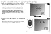
...176; downward tilt when mounted, see the next page for spacer installation instructions. Mounting Holes 2. ATTACHING THE TV HOOKS AND KICK STANDS 1. Open the pouch labeled with the size that fits. Place the 2 TV hooks (part B) against the top 2 mounting holes as ...M4, M5, M6, or M8. If you want to place a rug or blanket beneath the screen to prevent scratches. In your TV's User Guide...
...176; downward tilt when mounted, see the next page for spacer installation instructions. Mounting Holes 2. ATTACHING THE TV HOOKS AND KICK STANDS 1. Open the pouch labeled with the size that fits. Place the 2 TV hooks (part B) against the top 2 mounting holes as ...M4, M5, M6, or M8. If you want to place a rug or blanket beneath the screen to prevent scratches. In your TV's User Guide...

Quick Installation Guide
Page 18
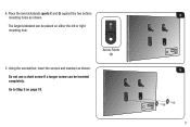
Using the screwdriver, insert the screws and washers as shown. 3 Because each TV is different, your TV to have a 9° downward tilt when mounted, use a short screw if a longer screw can be inserted completely. 16 Use screws that can be inserted completely. OPTIONAL: If you want your VIZIO TV mount includes screws of different lengths. Do not use the spacers (part G) and the longer screws when mounting the TV hooks. 3.
Using the screwdriver, insert the screws and washers as shown. 3 Because each TV is different, your TV to have a 9° downward tilt when mounted, use a short screw if a longer screw can be inserted completely. 16 Use screws that can be inserted completely. OPTIONAL: If you want your VIZIO TV mount includes screws of different lengths. Do not use the spacers (part G) and the longer screws when mounting the TV hooks. 3.
Quick Installation Guide
Page 19
Do not use a short screw if a longer screw can be inserted completely. Using the screwdriver, insert the screws and washers as shown. Arrow Points Up 4 5 17 4. The larger kickstand can be placed on page 18. Go to Step 5 on either the left or right mounting hole. 5. Place the two kickstands (parts C and D) against the two bottom mounting holes as shown.
Do not use a short screw if a longer screw can be inserted completely. Using the screwdriver, insert the screws and washers as shown. Arrow Points Up 4 5 17 4. The larger kickstand can be placed on page 18. Go to Step 5 on either the left or right mounting hole. 5. Place the two kickstands (parts C and D) against the two bottom mounting holes as shown.
Quick Installation Guide
Page 20
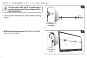
Turn the handle on the bar until the flat side of Bar Facing Wall 2. Bar Hang TV Hook on the bar as shown. To prevent injury to 1 yourself or damage to your TV, perform this step with the help of another person, lift the TV and hang the TV 2 hooks on Bar 18 Bar 1. With the help of another person. STEP 5 - Flat Side of the bar is facing the wall. HANGING THE TV ON THE MOUNT This step requires lifting the TV.
Turn the handle on the bar until the flat side of Bar Facing Wall 2. Bar Hang TV Hook on the bar as shown. To prevent injury to 1 yourself or damage to your TV, perform this step with the help of another person, lift the TV and hang the TV 2 hooks on Bar 18 Bar 1. With the help of another person. STEP 5 - Flat Side of the bar is facing the wall. HANGING THE TV ON THE MOUNT This step requires lifting the TV.

Quick Installation Guide
Page 22
... of VIZIO's commitment to save the locking tool. TECHNICAL SUPPORT Products are integral parts of operation: Monday - For more information on warranty service or repair, after the warranty period, please contact our Support Department at the number below. To remove the TV from the mount, perform Step 5 in the future. To attach the device, remove the security screw and...
... of VIZIO's commitment to save the locking tool. TECHNICAL SUPPORT Products are integral parts of operation: Monday - For more information on warranty service or repair, after the warranty period, please contact our Support Department at the number below. To remove the TV from the mount, perform Step 5 in the future. To attach the device, remove the security screw and...

Quick Installation Guide
Page 23
... no occurrence took place; Photo(s) of any additional damage claims. 21 Serial number. * Failure to perform in accordance with that bracket's specifications sheet or product manual. ** Properly installed in accordance with that bracket's installation instruction sheet or bracket manual and only when mounted on approved surfaces. ***VIZIO reserves the right to require additional supporting evidence to substantiate any claimed damage. This insurance is not provided to...
... no occurrence took place; Photo(s) of any additional damage claims. 21 Serial number. * Failure to perform in accordance with that bracket's specifications sheet or product manual. ** Properly installed in accordance with that bracket's installation instruction sheet or bracket manual and only when mounted on approved surfaces. ***VIZIO reserves the right to require additional supporting evidence to substantiate any claimed damage. This insurance is not provided to...
Quick Installation Guide
Page 24
VIZIO, THE V LOGO, WHERE VISION MEETS VALUE, AND OTHER VIZIO TRADEMARKS ARE THE INTELLECTUAL PROPERTY OF VIZIO INC. PRODUCT FEATURES AND SPECIFICATIONS ARE SUBJECT TO CHANGE WITHOUT NOTICE. © 2010 VIZIO INC. IMAGES USED ARE FOR ILLUSTRATION PURPOSES ONLY. ALL RIGHTS RESERVED. 100914ST-NC TRADEMARKS SHOWN ARE THE PROPERTY OF THEIR RESPECTIVE OWNERS.
VIZIO, THE V LOGO, WHERE VISION MEETS VALUE, AND OTHER VIZIO TRADEMARKS ARE THE INTELLECTUAL PROPERTY OF VIZIO INC. PRODUCT FEATURES AND SPECIFICATIONS ARE SUBJECT TO CHANGE WITHOUT NOTICE. © 2010 VIZIO INC. IMAGES USED ARE FOR ILLUSTRATION PURPOSES ONLY. ALL RIGHTS RESERVED. 100914ST-NC TRADEMARKS SHOWN ARE THE PROPERTY OF THEIR RESPECTIVE OWNERS.


