
Quickstart Guide English
Page 2
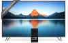
... your display close to a power outlet, power is used for the installation, use attachments/accessories specified by the manufacturer. • Use only with the cart, stand, tripod, bracket, or table specified by the manufacturer, or sold with the manufacturer's instructions. • Do not install near your display. A grounding type plug has...
... your display close to a power outlet, power is used for the installation, use attachments/accessories specified by the manufacturer. • Use only with the cart, stand, tripod, bracket, or table specified by the manufacturer, or sold with the manufacturer's instructions. • Do not install near your display. A grounding type plug has...
Quickstart Guide English
Page 6
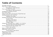
...your Tablet Remote...10 Charging your Tablet Remote...11 This is your basic remote...12 Inserting and replacing batteries...13 Installing the Display Stands...14 First-Time Setup...16 Sleep mode and unlocking the Tablet Remote 20 Getting familiar with Android™...21 Adding more Apps...22... Getting started with the VIZIO SmartCast™ app 24 Account Setup...24 Selecting a Cast device...25 Basic display functions...26 Category Pages...27 Using your smartphone or tablet...
...your Tablet Remote...10 Charging your Tablet Remote...11 This is your basic remote...12 Inserting and replacing batteries...13 Installing the Display Stands...14 First-Time Setup...16 Sleep mode and unlocking the Tablet Remote 20 Getting familiar with Android™...21 Adding more Apps...22... Getting started with the VIZIO SmartCast™ app 24 Account Setup...24 Selecting a Cast device...25 Basic display functions...26 Category Pages...27 Using your smartphone or tablet...

Quickstart Guide English
Page 14
Remove any sharp edges. To prevent scratches or damage to avoid damage. English - 14 Î P Make sure the top and bottom edges of the screen are being supported by the surface to the screen, place the display on a clean, flat surface. Installing the Display Stands 1 It is recommended that two people take part in the stand installation. Place the display screen-down on a soft surface such as a carpet, rug, or blanket, and avoid any plastic film from the Home Theater Display and stands.
Remove any sharp edges. To prevent scratches or damage to avoid damage. English - 14 Î P Make sure the top and bottom edges of the screen are being supported by the surface to the screen, place the display on a clean, flat surface. Installing the Display Stands 1 It is recommended that two people take part in the stand installation. Place the display screen-down on a soft surface such as a carpet, rug, or blanket, and avoid any plastic film from the Home Theater Display and stands.

Quickstart Guide English
Page 15
2 Insert the stands into the back of the display. Secure each stand to the display with two (2) Phillips screws (included). Insert the screws into the base of the display and tighten them using a Phillips screwdriver. When you are finished, place the display on a stable, level surface. Each stand is different and will only fit securely in the correct port. English - 15
2 Insert the stands into the back of the display. Secure each stand to the display with two (2) Phillips screws (included). Insert the screws into the base of the display and tighten them using a Phillips screwdriver. When you are finished, place the display on a stable, level surface. Each stand is different and will only fit securely in the correct port. English - 15

Quickstart Guide English
Page 32
... came with a UL-listed wall mount bracket rated for your display and wall mount to help you can scratch or damage the display. 3. Remove the stands by loosening and removing the screws. 4.
... came with a UL-listed wall mount bracket rated for your display and wall mount to help you can scratch or damage the display. 3. Remove the stands by loosening and removing the screws. 4.
Quickstart Guide English
Page 33
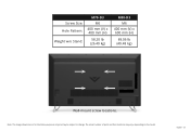
Screw Size: Hole Pattern: Weight w/o Stand: M70-D3 M6 400 mm (V) x 400 mm (H) 58.20 lb (26.40 kg) M80-D3 M6 400 mm (V) x 600 mm (H) 89.06 lb (40.48 kg) Wall-mount screw locations. English - 33 Note: The image shown here is for illustrative purposes only and may vary, depending on the model. The actual number of ports and their locations may be subject to change.
Screw Size: Hole Pattern: Weight w/o Stand: M70-D3 M6 400 mm (V) x 400 mm (H) 58.20 lb (26.40 kg) M80-D3 M6 400 mm (V) x 600 mm (H) 89.06 lb (40.48 kg) Wall-mount screw locations. English - 33 Note: The image shown here is for illustrative purposes only and may vary, depending on the model. The actual number of ports and their locations may be subject to change.


