Two-Page Specifications Sheet
Page 2
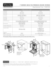
... is equipped with No. 10 ground wire in personal injury or damage to the wall or *Flush mount dimen installed flush to any adjacent appliances such as a microwave or warming dr1aw9-e1r/i2s "re(q4u9i.r5edcmfor) -veOnvtielartaiolln purposes... separately Max. 7 SERIES BUILT-IN FRENCH-DOOR OVENS ® Viking Professional 7 Series - Please ** The do not AHAM pStraenpdaarer2(6d5i4n-.f71so/tcr2am"ml)laetiaosnurfirnogmobv(er6on0c2.9ch4acu"mpre)...
... is equipped with No. 10 ground wire in personal injury or damage to the wall or *Flush mount dimen installed flush to any adjacent appliances such as a microwave or warming dr1aw9-e1r/i2s "re(q4u9i.r5edcmfor) -veOnvtielartaiolln purposes... separately Max. 7 SERIES BUILT-IN FRENCH-DOOR OVENS ® Viking Professional 7 Series - Please ** The do not AHAM pStraenpdaarer2(6d5i4n-.f71so/tcr2am"ml)laetiaosnurfirnogmobv(er6on0c2.9ch4acu"mpre)...
Installation Instructions
Page 1
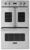
Installation Professional Built-In Electric Single and Double Ovens VESO1302 / VESO5272 / VESO5302 / VESO5302T VEDO1302 / VEDO5272 / VEDO5302 / VEDO530T CVESO1302 / CVESO5272 / CVESO5302 / CVESO5302T CVEDO1302 /C VEDO5272 / CVEDO5302 / CVEDO5302T Professional Built-In Electric Single and Double French Door Ovens VSOF730 / VDOF730 CVSOF730 / CVDOF730
Installation Professional Built-In Electric Single and Double Ovens VESO1302 / VESO5272 / VESO5302 / VESO5302T VEDO1302 / VEDO5272 / VEDO5302 / VEDO530T CVESO1302 / CVESO5272 / CVESO5302 / CVESO5302T CVEDO1302 /C VEDO5272 / CVEDO5302 / CVEDO5302T Professional Built-In Electric Single and Double French Door Ovens VSOF730 / VDOF730 CVSOF730 / CVDOF730
Installation Instructions
Page 2
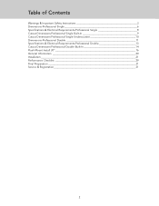
Table of Contents Warnings & Important Safety Instructions 3 Dimensions-Professional Single 6 Specifications & Electrical Requirements-Professional Single 8 Cutout Dimensions-Professional Single Built-In 9 Cutout Dimensions-Professional Single Undercounter 10 Dimensions-Professional Double 11 Specifications & Electrical Requirements-Professional Double 13 Cutout Dimensions-Professional Double Built-In 14 Flush Mount Install 30 16 General Information 20 Installation 21 Performance Checklist 29 Final Preparation 31 Service & Registration 31 2
Table of Contents Warnings & Important Safety Instructions 3 Dimensions-Professional Single 6 Specifications & Electrical Requirements-Professional Single 8 Cutout Dimensions-Professional Single Built-In 9 Cutout Dimensions-Professional Single Undercounter 10 Dimensions-Professional Double 11 Specifications & Electrical Requirements-Professional Double 13 Cutout Dimensions-Professional Double Built-In 14 Flush Mount Install 30 16 General Information 20 Installation 21 Performance Checklist 29 Final Preparation 31 Service & Registration 31 2
Installation Instructions
Page 3
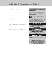
... personal injury or death CAUTION Hazards or unsafe practices which COULD result in this manual and on your appliance. In Canada: Installation must leave these instructions completely and carefully. • DO NOT remove permanently affixed labels, warnings, or plates from product. All... safety messages will be installed by the safety alert symbol and the word "DANGER," "WARNING" or "CAUTION." Always read these instructions with the current CSA C22...
... personal injury or death CAUTION Hazards or unsafe practices which COULD result in this manual and on your appliance. In Canada: Installation must leave these instructions completely and carefully. • DO NOT remove permanently affixed labels, warnings, or plates from product. All... safety messages will be installed by the safety alert symbol and the word "DANGER," "WARNING" or "CAUTION." Always read these instructions with the current CSA C22...
Installation Instructions
Page 4
... recommended) • On a dedicated circuit (no other receptacles, switches or loads in outdoor situations) • Protected from GFI outlets which are not installed properly or do not meet the requirements below. IMPORTANT- If the use of a GFI is required, it should be used if required by NFPA-70...state/local laws, or local ordinances. • The required use of a GFI is normally related to the location of water or moisture. • Viking Range, LLC will NOT warranty any problems resulting from moisture (water, steam, high humidity) as much as reasonably possible 4 Read and Follow!
... recommended) • On a dedicated circuit (no other receptacles, switches or loads in outdoor situations) • Protected from GFI outlets which are not installed properly or do not meet the requirements below. IMPORTANT- If the use of a GFI is required, it should be used if required by NFPA-70...state/local laws, or local ordinances. • The required use of a GFI is normally related to the location of water or moisture. • Viking Range, LLC will NOT warranty any problems resulting from moisture (water, steam, high humidity) as much as reasonably possible 4 Read and Follow!
Installation Instructions
Page 5
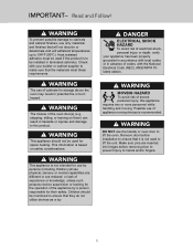
... of the appliance by persons (including children) whose physical, sensory or mental capabilities are different or are inserted into hinges before installation to ensure that the materials meet these requirements. stepping, sitting, or leaning on safety considerations. WARNING This appliance should be... installed in absence of electrical shock, personal injury or death; ANSI/NFPA 70latest edition. WARNING The use only materials and finishes ...
... of the appliance by persons (including children) whose physical, sensory or mental capabilities are different or are inserted into hinges before installation to ensure that the materials meet these requirements. stepping, sitting, or leaning on safety considerations. WARNING This appliance should be... installed in absence of electrical shock, personal injury or death; ANSI/NFPA 70latest edition. WARNING The use only materials and finishes ...
Installation Instructions
Page 8
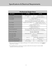
...-1/2" (74.9 cm) to cabinets **The AHAM Standard for Select and Premiere 30" W. ft. ft. VSOF730 4.3 cu. ft. 4.1 cu. ft. 4.7 cu. French door models cannot be installed flush to control panel-25-3/4" (65.4 cm) with door open (Select/Premiere Models)-46" (116.8 cm) with door open (French Door Models)-39-5/8" (100.6 cm...
...-1/2" (74.9 cm) to cabinets **The AHAM Standard for Select and Premiere 30" W. ft. ft. VSOF730 4.3 cu. ft. 4.1 cu. ft. 4.7 cu. French door models cannot be installed flush to control panel-25-3/4" (65.4 cm) with door open (Select/Premiere Models)-46" (116.8 cm) with door open (French Door Models)-39-5/8" (100.6 cm...
Installation Instructions
Page 10
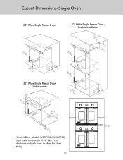
Cutout Dimensions-Single Oven 30" Wide Single French Door 30" Wide Single French Door Double Installation * 2(781-.41/c8m") 2(782-.41/c2m") (602.94c"m) * aMreakpeerspuerendwicaulllsar Min(.1t24o.-13fl/co4mo"r) JLuonBccoatxtiioonn (10.42"cm5()1"2.M7 icnm. ) 30" Wide Single French Door Undercounter * 2(...
Cutout Dimensions-Single Oven 30" Wide Single French Door 30" Wide Single French Door Double Installation * 2(781-.41/c8m") 2(782-.41/c2m") (602.94c"m) * aMreakpeerspuerendwicaulllsar Min(.1t24o.-13fl/co4mo"r) JLuonBccoatxtiioonn (10.42"cm5()1"2.M7 icnm. ) 30" Wide Single French Door Undercounter * 2(...
Installation Instructions
Page 13
... kg) *Flush mount dimensions are for measuring oven capacity subtracts the door plug and convection baffle dimension from the total oven volume. 13 Should be installed flush to control panel-25-3/4" (65.4 cm) with door open (Select/Premiere models)-46" (116.8 cm) with door open (French Door model)-39-1/2" (100.3 cm...
... kg) *Flush mount dimensions are for measuring oven capacity subtracts the door plug and convection baffle dimension from the total oven volume. 13 Should be installed flush to control panel-25-3/4" (65.4 cm) with door open (Select/Premiere models)-46" (116.8 cm) with door open (French Door model)-39-1/2" (100.3 cm...
Installation Instructions
Page 15
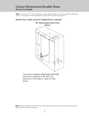
... above and below the oven to any adjacent appliances such as a microwave or warming drawer is required for ventilation purposes. (French Door models cannot be installed flush to cabinets) 30" Wide Double French Door Built-In * 2(782-.41/c2m") (15208-.65/c8m") (602.94c"m) * min(1.35t8o-.71fl/co4moa"Mr)reakpeerspuerendwicaulllsar JLuonBccoatxtiioonn...
... above and below the oven to any adjacent appliances such as a microwave or warming drawer is required for ventilation purposes. (French Door models cannot be installed flush to cabinets) 30" Wide Double French Door Built-In * 2(782-.41/c2m") (15208-.65/c8m") (602.94c"m) * min(1.35t8o-.71fl/co4moa"Mr)reakpeerspuerendwicaulllsar JLuonBccoatxtiioonn...
Installation Instructions
Page 16
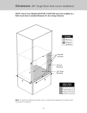
LEGEND Blocking Finished Surfaces Finished Surfaces F E Vertical Blocking 3/4" Base Blocking D SINGLE OVEN FLUSH CUTOUT D 29-15/16" (76.0 cm) E 25-3/4" (65.4 cm) F 30-5/16" (77.0 cm) Note: To install the professional custom oven in a flush mount application the flush mount accessory kit is required. 16 Dimensions (30" Single Oven flush mount installation) NOTE: French Door Models (VSOF730/ CVSOF730) cannot be installed as a flush mount due to needed allowance for door swing clearance.
LEGEND Blocking Finished Surfaces Finished Surfaces F E Vertical Blocking 3/4" Base Blocking D SINGLE OVEN FLUSH CUTOUT D 29-15/16" (76.0 cm) E 25-3/4" (65.4 cm) F 30-5/16" (77.0 cm) Note: To install the professional custom oven in a flush mount application the flush mount accessory kit is required. 16 Dimensions (30" Single Oven flush mount installation) NOTE: French Door Models (VSOF730/ CVSOF730) cannot be installed as a flush mount due to needed allowance for door swing clearance.
Installation Instructions
Page 17
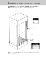
Dimensions (30" Double Oven flush mount installation) NOTE: French Door Models (VDOF730/ CVDOF730) cannot be installed as a flush mount due to needed allowance for door swing clearance. LEGEND Blocking Finished Surfaces Finished Surfaces Vertical C Blocking 3/4" Base Blocking B A DOUBLE OVEN FLUSH CUTOUT A 29-15/16" (76.0 cm) B 25-3/4" (65.4 cm) C 52-13/16" (134.1 cm) Note: To install the professional custom oven in a flush mount application the flush mount accessory kit is required. 17
Dimensions (30" Double Oven flush mount installation) NOTE: French Door Models (VDOF730/ CVDOF730) cannot be installed as a flush mount due to needed allowance for door swing clearance. LEGEND Blocking Finished Surfaces Finished Surfaces Vertical C Blocking 3/4" Base Blocking B A DOUBLE OVEN FLUSH CUTOUT A 29-15/16" (76.0 cm) B 25-3/4" (65.4 cm) C 52-13/16" (134.1 cm) Note: To install the professional custom oven in a flush mount application the flush mount accessory kit is required. 17

Installation Instructions
Page 18
Dimensions (30" Flush mount installation) NOTE: French Door Models cannot be installed as a flush mount due to needed allowance for door swing clearance. Top View Screw Distance will vary depending on the cabinet Vertical Blocking C Screw A 18 CRITICAL DIMENSIONS A 29-15/16" (76.0 cm) B 2-1/2" (6.4 cm) C 1/2" (1.3 cm) B
Dimensions (30" Flush mount installation) NOTE: French Door Models cannot be installed as a flush mount due to needed allowance for door swing clearance. Top View Screw Distance will vary depending on the cabinet Vertical Blocking C Screw A 18 CRITICAL DIMENSIONS A 29-15/16" (76.0 cm) B 2-1/2" (6.4 cm) C 1/2" (1.3 cm) B

Installation Instructions
Page 19
Dimensions (30" Flush mount installation) NOTE: French Door Models cannot be installed as a flush mount due to needed allowance for door swing clearance. Side View Vertical Blocking LEGEND Blocking Cabinet Cross Section CRITICAL DIMENSIONS B B 2-1/2" (6.4 cm) D D 3" (7.6 cm) Base Blocking 19
Dimensions (30" Flush mount installation) NOTE: French Door Models cannot be installed as a flush mount due to needed allowance for door swing clearance. Side View Vertical Blocking LEGEND Blocking Cabinet Cross Section CRITICAL DIMENSIONS B B 2-1/2" (6.4 cm) D D 3" (7.6 cm) Base Blocking 19
Installation Instructions
Page 20
... the appliance should be sealed. • Keep appliance area clear and free from the cooling fan, contact an authorized service center before installation to lift the unit. CAUTION The cooling fan should be operating when the unit is heavy - CAUTION Avoid any damage to lift the...is not operating or you are screwed to the bottom of the corrugated cover. • Remove the corrugated cover by lifting it is installed. Do not remove the French Door model top oven/single oven doors. Recommendations for optimal oven performance. General Information • All ...
... the appliance should be sealed. • Keep appliance area clear and free from the cooling fan, contact an authorized service center before installation to lift the unit. CAUTION The cooling fan should be operating when the unit is heavy - CAUTION Avoid any damage to lift the...is not operating or you are screwed to the bottom of the corrugated cover. • Remove the corrugated cover by lifting it is installed. Do not remove the French Door model top oven/single oven doors. Recommendations for optimal oven performance. General Information • All ...
Installation Instructions
Page 21
...free from combustible materials, gasoline and other flammable vapors. • WARNING: DO NOT USE AN EXTENSION CORD WITH THIS APPLIANCE. Remove door before installation to ensure that support for this appliance. • WARNING: DO NOT use the handle or oven door to lift the unit. Make sure... pins are inserted into hinges before you perform the installation. • Use of a hydraulic lift is recommended that a thorough site inspection be conducted PRIOR to unpacking and moving this appliance is perpendicular ...
...free from combustible materials, gasoline and other flammable vapors. • WARNING: DO NOT USE AN EXTENSION CORD WITH THIS APPLIANCE. Remove door before installation to ensure that support for this appliance. • WARNING: DO NOT use the handle or oven door to lift the unit. Make sure... pins are inserted into hinges before you perform the installation. • Use of a hydraulic lift is recommended that a thorough site inspection be conducted PRIOR to unpacking and moving this appliance is perpendicular ...
Installation Instructions
Page 22
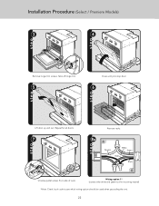
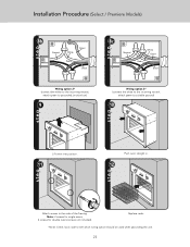
Take off hinge trim. 5 Close until pins stop door. 6 Lift door up and out. Repeat for all doors. 7 Remove racks. 8a Neutral White Green Red Black Unscrew pallet screws from side of oven. Installation Procedure (Select / Premiere Models) 3 4 Remove hinge trim screws. Wiring option 1* (connect the white and green to the incoming neutral) *Note: Check local code to see which wiring option should be used when grounding the unit. 22
Take off hinge trim. 5 Close until pins stop door. 6 Lift door up and out. Repeat for all doors. 7 Remove racks. 8a Neutral White Green Red Black Unscrew pallet screws from side of oven. Installation Procedure (Select / Premiere Models) 3 4 Remove hinge trim screws. Wiring option 1* (connect the white and green to the incoming neutral) *Note: Check local code to see which wiring option should be used when grounding the unit. 22
Installation Instructions
Page 23
Note: 2 screws for single ovens, 4 screws for double ovens (screws not included). Installation Procedure (Select / Premiere Models) 8b Neutral White Green Red Black Wiring option 2* (connect the white to the incoming neutral, attach green to grounded junction box) 9 ...
Note: 2 screws for single ovens, 4 screws for double ovens (screws not included). Installation Procedure (Select / Premiere Models) 8b Neutral White Green Red Black Wiring option 2* (connect the white to the incoming neutral, attach green to grounded junction box) 9 ...
Installation Instructions
Page 24
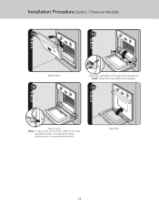
Put hinge trim plates back on. Turn adjustment screw clockwise (up) or counterclockwise (down). Note: To adjust door, unit must be pulled out to be re-aligned. 16 Take out pins. Note: Screw holes may need to access adjustment screws. Close door. 24 Installation Procedure (Select / Premiere Models) 13 14 Replace door. 15 Open door completely.
Put hinge trim plates back on. Turn adjustment screw clockwise (up) or counterclockwise (down). Note: To adjust door, unit must be pulled out to be re-aligned. 16 Take out pins. Note: Screw holes may need to access adjustment screws. Close door. 24 Installation Procedure (Select / Premiere Models) 13 14 Replace door. 15 Open door completely.
Installation Instructions
Page 25
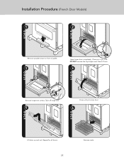
Place pin in pin hole. Take off hinge trim. 5 1 2 Open lower door completely. Repeat for all doors. 25 Remove racks. DO NOT remove the top/single oven French Doors. 4 Close until pins stop door. 6 Lift door up and out. Installation Procedure (French Door Models) 1 2 Remove wooden brace on front of pallet. 3 2 2 1 Remove hinge trim screws.
Place pin in pin hole. Take off hinge trim. 5 1 2 Open lower door completely. Repeat for all doors. 25 Remove racks. DO NOT remove the top/single oven French Doors. 4 Close until pins stop door. 6 Lift door up and out. Installation Procedure (French Door Models) 1 2 Remove wooden brace on front of pallet. 3 2 2 1 Remove hinge trim screws.