
User Manual
Page 2
..., manual or otherwise without obligation to the products described in regard to this document. Award BIOS is a registered trademark of VIA Technologies. Copyright Copyright © 2010-2012 VIA Technologies Incorporated. Disclaimer No license is believed to be reproduced, transmitted, transcribed, stored in ... patent or patent rights of IBM Corporation. PS/2 is a registered trademark of VIA Technologies, Incorporated. Trademarks All trademarks are subject to change . VIA Technologies makes no responsibility for any patent infringements that may be accurate and reliable...
..., manual or otherwise without obligation to the products described in regard to this document. Award BIOS is a registered trademark of VIA Technologies. Copyright Copyright © 2010-2012 VIA Technologies Incorporated. Disclaimer No license is believed to be reproduced, transmitted, transcribed, stored in ... patent or patent rights of IBM Corporation. PS/2 is a registered trademark of VIA Technologies, Incorporated. Trademarks All trademarks are subject to change . VIA Technologies makes no responsibility for any patent infringements that may be accurate and reliable...

User Manual
Page 6
... 2 9 Installation 9 CPU 10 Memory Module Installation 14 Connecting the Power Supply 17 Back Panel Ports 19 Connectors 23 Jumpers 38 Slots 41 Chapter 3 43 BIOS Setup 43 Entering Setup 44 Control Keys 45 Navigating the BIOS Menus 46 Getting Help 47 Main Menu 48 Standard CMOS Features 50 IDE Drives 51 Advanced...
... 2 9 Installation 9 CPU 10 Memory Module Installation 14 Connecting the Power Supply 17 Back Panel Ports 19 Connectors 23 Jumpers 38 Slots 41 Chapter 3 43 BIOS Setup 43 Entering Setup 44 Control Keys 45 Navigating the BIOS Menus 46 Getting Help 47 Main Menu 48 Standard CMOS Features 50 IDE Drives 51 Advanced...

User Manual
Page 11
... Fan and System Fan) • 1 x +12V power connector • 1 x SMBus connector • 1 x LVDS (function to be supported w/ an additional daughter card) • 1 x WP pin header BIOS • • Award BIOS with 4/8Mbit flash memory capacity ACPI2.0, SMBIOS2.1 and DMI2.2 Form Factor • Mini-ITX (6 layers) • 17 cm X 17 cm 3
... Fan and System Fan) • 1 x +12V power connector • 1 x SMBus connector • 1 x LVDS (function to be supported w/ an additional daughter card) • 1 x WP pin header BIOS • • Award BIOS with 4/8Mbit flash memory capacity ACPI2.0, SMBIOS2.1 and DMI2.2 Form Factor • Mini-ITX (6 layers) • 17 cm X 17 cm 3

User Manual
Page 12
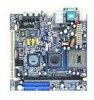
Chapter 1 MAINBOARD LAYOUT Top: Mouse Bottom: Keyboard Top: COM1 Bottom: VGA port Top: RJ45 port Bottom: USB port S-Video port RCA Jack Line-Out Line-In Microphone ATXPWR KBMS +12V_PWR C3TM Processor CPUFAN SYSFAN DIMM1 SMBus CN400 LVDS VT8237R-series SPDIF_SEL1 COM2 FIR LPT USB 3/4 USB 5/6 USB 7/8 F_AUDIO CD_IN SPDIF 1394_1 BIOS Socket WP CLEAR_CMOS CMOS battery PCI Slot SATA_1 SATA_2 WOL VIP_2 J1 IDE1 IDE2 F_PANEL 4
Chapter 1 MAINBOARD LAYOUT Top: Mouse Bottom: Keyboard Top: COM1 Bottom: VGA port Top: RJ45 port Bottom: USB port S-Video port RCA Jack Line-Out Line-In Microphone ATXPWR KBMS +12V_PWR C3TM Processor CPUFAN SYSFAN DIMM1 SMBus CN400 LVDS VT8237R-series SPDIF_SEL1 COM2 FIR LPT USB 3/4 USB 5/6 USB 7/8 F_AUDIO CD_IN SPDIF 1394_1 BIOS Socket WP CLEAR_CMOS CMOS battery PCI Slot SATA_1 SATA_2 WOL VIP_2 J1 IDE1 IDE2 F_PANEL 4

User Manual
Page 15
... 28-29 36-37 25 33 12 30 35 31 ONBOARD JUMPERS Jumper CLEAR_CMOS J1 SPDIF_SEL WP Description Reset CMOS settings IDE selector S/PDIF selector BIOS write protection setting Page 38-39 38, 40 38, 40 38, 40 7
... 28-29 36-37 25 33 12 30 35 31 ONBOARD JUMPERS Jumper CLEAR_CMOS J1 SPDIF_SEL WP Description Reset CMOS settings IDE selector S/PDIF selector BIOS write protection setting Page 38-39 38, 40 38, 40 38, 40 7

User Manual
Page 36
Chapter 2 Fast IrDA Infrared Module Connector: FIR This pin header is used to connect to activate the IR function. Pin Signal 1 +5V 2 IRRX1 3 IRRX 4 GND 5 IRTX Description VCC FIR/SIR Data Receive SIR Data Receive Ground FIR/SIR Data Transmit C3TM Processor CN400 1 FIR VT8237R 1 LPT 1 SPDIF 28 The BIOS settings must be configured to an IrDA module.
Chapter 2 Fast IrDA Infrared Module Connector: FIR This pin header is used to connect to activate the IR function. Pin Signal 1 +5V 2 IRRX1 3 IRRX 4 GND 5 IRTX Description VCC FIR/SIR Data Receive SIR Data Receive Ground FIR/SIR Data Transmit C3TM Processor CN400 1 FIR VT8237R 1 LPT 1 SPDIF 28 The BIOS settings must be configured to an IrDA module.

User Manual
Page 47
Keep cap on CLEAR_CMOS jumper default position. Hold down the key during the boot process and enter BIOS setup to pins 2-3. Caution: Except when clearing the RTC RAM, never remove the cap on pins 2-3 for about 5~10 seconds, then move the cap back ...
Keep cap on CLEAR_CMOS jumper default position. Hold down the key during the boot process and enter BIOS setup to pins 2-3. Caution: Except when clearing the RTC RAM, never remove the cap on pins 2-3 for about 5~10 seconds, then move the cap back ...

User Manual
Page 48
Pin Signal 1 DOM_Power 2 +5V 3 DOM_Power 4 +3.3V 1 1 1-2: +5V (Default) 3-4: +3.3V BIOS Write Protection: WP This jumper allows you to the IDE device. Chapter 2 PS2 Header: KBMS (Keyboard Mouse) When the pin header is not in...). 1 1 1-2: RCA Video 3-4: S/PDIF (Default) Voltage Selector: J1 The 20th pin on both IDE connectors can select either 3.3V or 5V to protect from flashing the BIOS. BIOS 1 Write Protection setting: pin1 = /WP & /TBL, pin2 = GND, short 1-2 (default) WP 40 For TV-out composite function, please short 1-2. Pin Signal 1 +5V 3 KB_CLK 5 EXT_KBCLK...
Pin Signal 1 DOM_Power 2 +5V 3 DOM_Power 4 +3.3V 1 1 1-2: +5V (Default) 3-4: +3.3V BIOS Write Protection: WP This jumper allows you to the IDE device. Chapter 2 PS2 Header: KBMS (Keyboard Mouse) When the pin header is not in...). 1 1 1-2: RCA Video 3-4: S/PDIF (Default) Voltage Selector: J1 The 20th pin on both IDE connectors can select either 3.3V or 5V to protect from flashing the BIOS. BIOS 1 Write Protection setting: pin1 = /WP & /TBL, pin2 = GND, short 1-2 (default) WP 40 For TV-out composite function, please short 1-2. Pin Signal 1 +5V 3 KB_CLK 5 EXT_KBCLK...

User Manual
Page 51
CHAPTER 3 BIOS Setup This chapter gives a detailed explanation of the BIOS setup functions. 43
CHAPTER 3 BIOS Setup This chapter gives a detailed explanation of the BIOS setup functions. 43

User Manual
Page 52
If you missed the BIOS setup entry point, you may restart the system and try again. 44 Chapter 3 ENTERING SETUP Power on the computer and press during the beginning of the boot sequence to enter the BIOS setup menu.
If you missed the BIOS setup entry point, you may restart the system and try again. 44 Chapter 3 ENTERING SETUP Power on the computer and press during the beginning of the boot sequence to enter the BIOS setup menu.

User Manual
Page 53
BIOS Setup CONTROL KEYS Keys Up Arrow Down Arrow Left Arrow Right Arrow Enter Escape Page Up / + Page Down / F1 F5 F6 F7 F9 F10 Description ...
BIOS Setup CONTROL KEYS Keys Up Arrow Down Arrow Left Arrow Right Arrow Enter Escape Page Up / + Page Down / F1 F5 F6 F7 F9 F10 Description ...

User Manual
Page 54
Chapter 3 NAVIGATING THE BIOS MENUS The main menu displays all the BIOS setup categories. Press to select any item/sub-menu. Use the control keys Up/Down arrow keys to display the sub-menu. To exit the submenu, press . 46 Description of the selected/highlighted category is available (see figure below). An arrow symbol next to a field indicates that a sub-menu is displayed at the bottom of the screen.
Chapter 3 NAVIGATING THE BIOS MENUS The main menu displays all the BIOS setup categories. Press to select any item/sub-menu. Use the control keys Up/Down arrow keys to display the sub-menu. To exit the submenu, press . 46 Description of the selected/highlighted category is available (see figure below). An arrow symbol next to a field indicates that a sub-menu is displayed at the bottom of the screen.

User Manual
Page 55
Press to exit the help screen displays the keys for using and navigating the BIOS setup. The help screen. 47 BIOS Setup GETTING HELP The BIOS setup program provides a "General Help" screen. You can display this screen from any menu/sub-menu by pressing .
Press to exit the help screen displays the keys for using and navigating the BIOS setup. The help screen. 47 BIOS Setup GETTING HELP The BIOS setup program provides a "General Help" screen. You can display this screen from any menu/sub-menu by pressing .

User Manual
Page 56
...advanced features available on your system. PC Health Status This menu shows the PC health status. 48 AwardBIOS CMOS Setup Utility Standard CMOS Features Advanced BIOS Features Advanced Chipset Features Integrated Peripherals Power Management Setup PnP / PCI Configurations PC Health Status Frequency / Voltage Control Load Fail-Safe Defaults Load Optimized... Defaults Set Supervisor Password Set User Password Save & Exit Setup Exit Without Saving ESC : Quit F9 : Menu in BIOS F10 : Save & Exit Setup : Select Item Time, Date, Hard Disk Type... Advanced...
...advanced features available on your system. PC Health Status This menu shows the PC health status. 48 AwardBIOS CMOS Setup Utility Standard CMOS Features Advanced BIOS Features Advanced Chipset Features Integrated Peripherals Power Management Setup PnP / PCI Configurations PC Health Status Frequency / Voltage Control Load Fail-Safe Defaults Load Optimized... Defaults Set Supervisor Password Set User Password Save & Exit Setup Exit Without Saving ESC : Quit F9 : Menu in BIOS F10 : Save & Exit Setup : Select Item Time, Date, Hard Disk Type... Advanced...

User Manual
Page 57
... exit setup. 49 BIOS Setup Frequency/Voltage Control Use this menu to set the BIOS user password. Set User Password Use this menu option to load BIOS default settings for minimal and stable system operations. Set Supervisor Password Use this menu option to set the BIOS supervisor password. Save ...& Exit Setup Save BIOS setting changes and exit setup. Load Fail-Safe Defaults Use this menu option to set the system frequency and voltage ...
... exit setup. 49 BIOS Setup Frequency/Voltage Control Use this menu to set the BIOS user password. Set User Password Use this menu option to load BIOS default settings for minimal and stable system operations. Set Supervisor Password Use this menu option to set the BIOS supervisor password. Save ...& Exit Setup Save BIOS setting changes and exit setup. Load Fail-Safe Defaults Use this menu option to set the system frequency and voltage ...
User Manual
Page 59
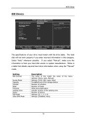
... this category. AwardBIOS CMOS Setup Utility IDE Channel 0 Master [Press Enter] Item Help [Auto] [Auto] 0 MB Menu Level To auto-detect the HDD's size, head... BIOS Setup IDE DRIVES IDE HDD Auto-Detection IDE Channel 0 Master Access Mode Capacity Cylinder Head Precomp Landing Zone Sector PIO Mode Ultra DMA Mode Phoenix...
... this category. AwardBIOS CMOS Setup Utility IDE Channel 0 Master [Press Enter] Item Help [Auto] [Auto] 0 MB Menu Level To auto-detect the HDD's size, head... BIOS Setup IDE DRIVES IDE HDD Auto-Detection IDE Channel 0 Master Access Mode Capacity Cylinder Head Precomp Landing Zone Sector PIO Mode Ultra DMA Mode Phoenix...
User Manual
Page 60
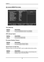
AwardBIOS CMOS Setup Utility Advanced BIOS Features Hard Disk Boot Priority Virus Warning CPU Internal Cache Processor Number Feature Quick Power On Self Test First Boot Device Second Boot Device Third ... up time. Setting Enabled Disabled Description Shorten Power On Self Test (POST) cycle and bootup time Standard Power On Self Test (POST) 52 Chapter 3 ADVANCED BIOS FEATURES Phoenix -
AwardBIOS CMOS Setup Utility Advanced BIOS Features Hard Disk Boot Priority Virus Warning CPU Internal Cache Processor Number Feature Quick Power On Self Test First Boot Device Second Boot Device Third ... up time. Setting Enabled Disabled Description Shorten Power On Self Test (POST) cycle and bootup time Standard Power On Self Test (POST) 52 Chapter 3 ADVANCED BIOS FEATURES Phoenix -
User Manual
Page 61
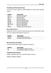
... Boot from network drive Disable the boot device sequence Boot Other Device Enables the system to boot from the "First/Second/Third Boot Device" list. BIOS Setup First/Second/Third Boot Device Set the boot device sequence as arrow keys Typematic Rate Setting Enables "Typematic Rate" and "Typematic Delay" functions. Setting... On Off Description Forces keypad to behave as 10-key Forces keypad to behave as BIOS attempts to boot from alternate devices if the system fails to load the disk operating system.
... Boot from network drive Disable the boot device sequence Boot Other Device Enables the system to boot from the "First/Second/Third Boot Device" list. BIOS Setup First/Second/Third Boot Device Set the boot device sequence as arrow keys Typematic Rate Setting Enables "Typematic Rate" and "Typematic Delay" functions. Setting... On Off Description Forces keypad to behave as 10-key Forces keypad to behave as BIOS attempts to boot from alternate devices if the system fails to load the disk operating system.
User Manual
Page 62
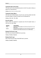
Setting Setup System Description Password prompt appears only when end users try to run BIOS Setup Password prompt appears every time when the computer is required every time the System boots, or only when you enter Setup. Settings: [Enabled, Disabled] ... on and when end users try to repeat the signal from a depressed key. Settings: [Enabled, Disabled] Display Small Logo Show small energy star logo during BIOS boot up process. Chapter 3 Typematic Rate (Chars/Sec) This item sets the rate (characters/second) at which the system retrieves a signal from the depressed key...
Setting Setup System Description Password prompt appears only when end users try to run BIOS Setup Password prompt appears every time when the computer is required every time the System boots, or only when you enter Setup. Settings: [Enabled, Disabled] ... on and when end users try to repeat the signal from a depressed key. Settings: [Enabled, Disabled] Display Small Logo Show small energy star logo during BIOS boot up process. Chapter 3 Typematic Rate (Chars/Sec) This item sets the rate (characters/second) at which the system retrieves a signal from the depressed key...

User Manual
Page 63
Pri. Master : 4. USB-HDD0 : 6. BIOS Setup HARD DISK BOOT PRIORITY Phoenix - Slave : 3. USB-HDD1 : 7. AwardBIOS CMOS Setup Utility Hard Disk Boot Priority 1. Master : 2. Press to move it down the list. Sec. Slave : 5. Bootable Add-In Cards Item Help Menu Level Use < > or < > to select a device, then press < + > to move it up, or < - > to exit this menu. : Move Enter: Select F5: Previous Values +/-/PU/PD: Value F10: Save F6: Fail-Safe Defaults ESC: Exit F1: General F7: Optimized Defaults Help 55 USB-HDD2 : 8. Pri. Sec.
Pri. Master : 4. USB-HDD0 : 6. BIOS Setup HARD DISK BOOT PRIORITY Phoenix - Slave : 3. USB-HDD1 : 7. AwardBIOS CMOS Setup Utility Hard Disk Boot Priority 1. Master : 2. Press to move it down the list. Sec. Slave : 5. Bootable Add-In Cards Item Help Menu Level Use < > or < > to select a device, then press < + > to move it up, or < - > to exit this menu. : Move Enter: Select F5: Previous Values +/-/PU/PD: Value F10: Save F6: Fail-Safe Defaults ESC: Exit F1: General F7: Optimized Defaults Help 55 USB-HDD2 : 8. Pri. Sec.